Multitec
Never use the pump itself as an anchorage point
for the piping. The forces and moments transmitted
to the pump flanges by the piping system (torsion, thermal
expansion, ...) must not exceed the permissible forces and
moments.
The pipelines must be anchored in close proximity to the pump
and connected without transmitting any stresses or strains. Their
weight must not act on the pump unit.
In case welding must be done on the piping when
the pumps are already installed, the device used
for electric welding may not be earthed on the pump or the
baseplate so that current flowing through the rolling element
bearings is avoided, which could cause their premature
destruction (pitting effect).
Thermal expansion of the pipelines must be compensated by
appropriate measures so as not to impose any extra loads on
the pump exceeding the permissible pipelines forces and
moments.
It may be necessary to provide expansion joints. An excessive,
impermissible increase in the pipeline forces may cause leaks
on the pump where the medium handled can escape into the
atmosphere.
Danger of life when hot media are handled !
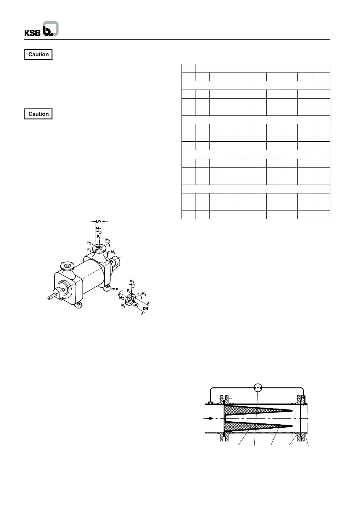
Fig. 5.4-1 Max. forces and moments at the pump nozzles
Direction of forces :
X = horizontal, parallel to the pump axis
Y = vertical to the pump axis
Z = horizontal, at a right angle to the pump axis
Direction of moments :
MX = around the horizontal axis, parallel to the pump axis
MY = around the vertical nozzle axis
MZ = around the horizontal axis, at a right angle to the
pump axis
Suction and discharge nozzle are regarded separately.
Max. permissible pipeline forces
(Material identification No. 10, 11, 12)
Nom. nozzle diameter
32 50 65 80 100 125 150 200 250
Vertical nozzle, at a right angle to the shaft (N)
Fx 245 510 640 700 1015 1470 1780 2700 -
Fy 410 635 800 970 1270 1850 2220 3490 -
Fz 265 415 520 625 830 1220 1465 2220 -
Horizontal nozzle, at a right angle to the shaft (N)
Fx 245 510 640 800 1015 1470 1780 2700 -
Fy 265 415 520 625 830 1220 1465 2220 -
Fz 410 635 800 970 1270 1850 2220 3490 -
Axial nozzle, parallel to the shaft (N)
Fx - - 800 - 1270 1850 2220 3490 4760
Fy - - 520 - 830 1220 1465 2220 3180
Fz - - 640 - 1015 1470 1780 2700 3810
Moments for all nozzles (Nm)
Mx 260 330 460 680 950 1235 1640 2520 3580
My 160 250 350 520 715 930 1260 1840 2710
Mz 190 170 240 340 490 660 840 1260 1740
Multitec 50 with radial suction nozzle
Example :
- for the suction nozzle, the values given in table column DN
80 apply.
- for the discharge nozzle, the values given in table column DN
50 apply.
Max. permissible pipeline forces
(Material identification Nos. 20-30)
The values given for the material identification nos. 10, 11, 12,
shall be multiplied by the factor 1.4.
Protection against foreign matter
Before commissioning new installations thoroughly clean, flush
and blow through all vessels, pipelines and connections. Often
welding beads, scales and other impurities only come off after a
certain period of operation. Fit a strainer in the suction line to
prevent them from entering the pump. The total cross section of
the holes in the strainer shall be three times the cross section of
the pipeline in order to avoid excessive pressure loss across
the strainer due to clogging. Conical strainers with laid-in wire
mesh having a mesh width of 2.0 mm and a wire diameter of 0.5
mm, of corrosion-resistant material, shall be used.
1 Strainer housing
2 Fine screen
3 Perforated plate
4 Pump suction nozzle
5 Differential pressure gauge
Fig. 5.4-2 Conical strainer for the suction line
6
2 5 3 1 4