Multitec
7.4.1 Tightening Torques - Tie Bolts 905
Material codes 10, 11, 12 (casing : cast iron)
Pump size Tightening torque (Nm)
Multitec 32 85
Multitec 50 140
Multitec 65 250
Multitec 100 395
Multitec 125 600
Multitec 150 700
Material codes 20, 21, 22, 23, 30
(casing : steel or stainless steel)
7.4.2 Reassembly of Hydraulic System
Pump reassembly starts at the suction side and proceeds
towards the discharge side. It is advisable to place the pump in
vertical position for reassembly. The sequence of reassembly
does not pose special problems and should be done according
to detailed sectional drawings showing the list if individual parts.
The components shall be re-installed in the same place as before
dismantling.
A clearance of 0.7 to 1.2 mm shall be set between the last impeller
230.1 or 230.3 and the balance drum 59-4 (or spacer sleeve
525.4).
- Tighten the nuts of the tie bolts 905 gently, with the pump in
vertical position.
- Place the pump in horizontal position upon its feet on the
assembly table.
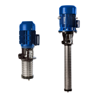
- Tighten the nuts of tie bolts 905 in two steps (first step : 50%
of nominal torque, second step : nominal torque) in the
sequence 1.4.2.3.
Fig. 7.4-1
7.4.3 Seals
Gland packing
Before re-packing, thoroughly clean the gland packing chamber
and the gland cover.
Packing rings must be inserted so that the cut edge
is displaced by approx. 9_to 120_in relation to the
previous one.
Slip the prestressed packing rings onto the shaft protecting sleeve,
press home the first packing ring with the help of the gland
follower. Each packing ring must be pressed into the packing
chamber individually, using the gland cover.
For gland packings with lantern ring (for use in vacuum operation),
the lantern ring is mounted instead of the next to last packing
ring (the last packing ring is located in the seal chamber on the
pump size).
The gland cover must be tightened by hand at first. Use a feeler
gauge to check the level position of the gland cover. It must be
easy to rotate the rotor by hand.
Leakage is normal during pump commissioning. After approx. 5
minutes’ operating period, the amount of leakage can be reduced
by steadily tightening the nuts of the gland cover by 1/6 of a turn.
Keep an eye on the amount of leakage and the water temperature.
It takes several hours of pump operation for the gland to be
adjusted completely. There must be a high leakage rate during
the running-in period.
Repeat this procedure every five minutes until a minimum value
is reached.
Pump size Operating pressure Tightening torque
(bar) (Nm)
Multitec 32 150
Multitec 50 240
Multitec 65 All 430
Multitec 100 680
Multitec 125 1370
Multitec 150
< 40 1500
> 40 2000
Dimensions in mm Pump size
32 - 50 - 65 100 125 150
Packing cross-
10 o 12.5 o 16 o
section
Length of packing
~ 181 ~ 223 ~ 243 ~ 306
cord
Number of packing
5 6
rings
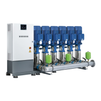
Gland housing
Pump size di da I
32 - 50 - 65 45 65 50
100 56 80 60
125 66 90 72
150 78 110 96
Fig. 7.4-2 Gland chamber dimensions
Mechanical Seals
Mechanical seals are precision components. The
seat ring and the spring-loaded ring must always
be replaced together, i.e. always replace the entire mechanical
seal.
To ensure trouble-free operation of the mechanical seal. The seal
faces and any tools used must be absolutely clean. Mechanical
seals must be installed with utmost care.
The seal faces shall only be cleaned immediately before assembly
takes place. They must not be greasy (grease, smudges ...) or
damaged.
18