Multitec
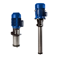
5.4.1 Vacuum Balance Line
Where liquid has to be pumped out of a vessel under vacuum, it
is advisable to install a vacuum balance line. This is should have
a nominal size of at least 25 mm and must be arranged to lead
into the vessel at a point above the highest permissible liquid
level.
An additional pipeline fitted with a shut-off valve - from the pump
discharge nozzle to the balance line - facilitates venting of the
pump before start-up.
5.5 Connection to Power supply
Connection to the power supply must be effected by a
trained electrician only (see 5.1). The applicable DIN VDE
regulations must be complied with.
Check available mains voltage against the data on the motor
rating plate and select appropriate start-up method.
Connection to the power supply must be effected in accordance
with the technical regulations of the responsible local energy
supply company.
We strongly recommend to use a motor protection switch.
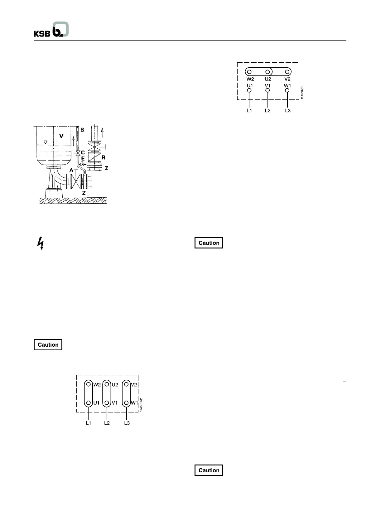
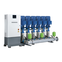
5.5.1 Connecting the Motor
Connect the motor in accordance with the circuit diagram in the
terminal box or as illustrated in Fig. 5.5-1 / Fig. 5.5-2.
Prior to starting the motor, check whether the
connection of the terminals is tight and re-tighten
possibly loose wires.
starting (low voltage)
Fig. 5.5-1 Connection diagram for three-phase motors,
starting
Y starting (high voltage)
Fig. 5.5-2 Connection diagram for three-phase motors,
Y starting
5.5.2 Setting the Time-Lag Relay
Make sure that in the case of three-phase motors with star-delta
starting method switching over from star to delta will be effected
at very short intervals. Prolonged switch-over intervals may result
in pump damage.
Time-lag relay setting recommended for star-delta starting :
3-5 seconds, depending on motor rating.
EN 50014 (Regulation DIN VDE 0170/0171 Part 1) stipulates
that explosion-proof motors, type of protection IP 54, “increased
safety” (Ex)e, thermal class T3, must always be connected via
a motor protection switch.
5.5.3 Checking the Direction of Rotation
On pumps fitted with uni-directional mechanical
seals (seal codes 62 and 63) the direction of
rotation must never be checked with the pump coupled to the
motor. If the motor and pump need not be de-coupled, make sure
that the pump has been primed before checking the direction of
rotation.
The motor’s direction of rotation must correspond to the direction
indicated by the arrow on the pump resp. motor (clockwise when
seen from the motor end; on version D anti-clockwise). This can
be verified by switching the motor on and then off again
immediately.
If the unit runs in the wrong direction of rotation, interchange two
of the three phases L1, L2 or L3 of the power supply cable in the
motor terminal box.
6. Commissioning, Start-up / Shutdown
Additional information for boiler feed pump operation.
Limit values for boiler fed water and condensate when using cast
iron pump parts : pH-value 9.0 (value aimed at 9.3) O
2
content <
0.02 ppm.
Before entry into the pump, these values must be guaranteed for
all operating conditions. The fresh water content has to amount
to max. 25%.
Water treatment shall be in accordance with the VdTÜV guidelines
for feed and boiler water in steam plants of up to 64 bar.
The penetration of air into the system must be avoided by all
means.
6.1 Commissioning
Before starting up the pump make sure that the
following requirements have been met :
- The quality of the concrete foundation is in compliance with
the applicable regulations.
A Main shut-off valve
B Vacuum balance line
C Shut-off valve
E Vacuum-tight shut-off valve
R Swing check valve
V Vessel under vacuum
Z Intermediate flange
Fig. 5.4-3 Suction line and vacuum balance line
7