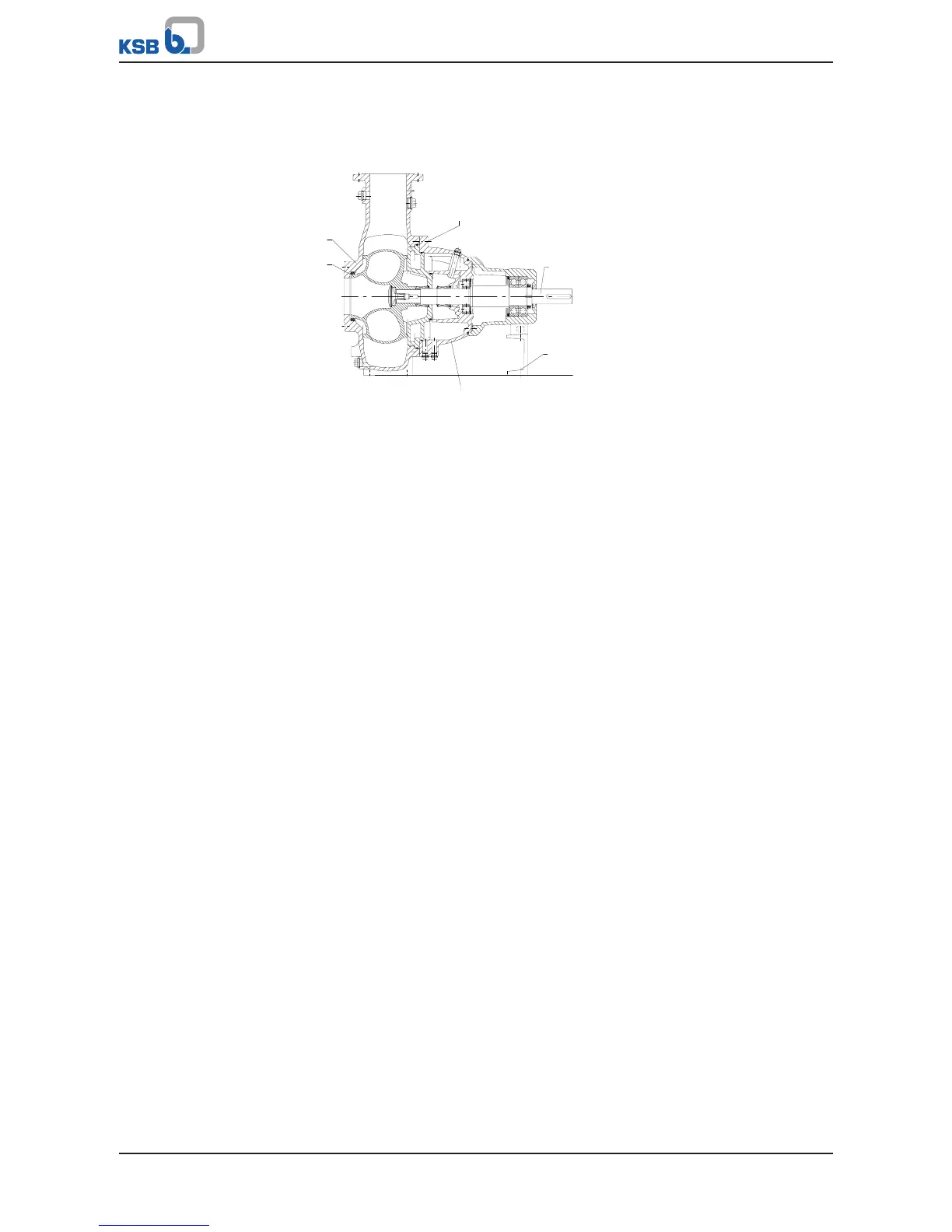
Fig.27: Removing the back pull-out unit
ü The lubricant chamber has been drained of all lubricant.
ü Transport equipment and lifting tackle are available.
ü An area for the back pull-out unit has been prepared.
1. Remove the coupling guard.
2. Remove the coupling spacer, if any.
3. Remove the drive, if required.
4. Loop a rope tightly around the bearing bracket.
5. Undo bolts 901.61 and discs 550.61 fastening the support foot.
6. Undo screwed connection 902.01/920.01. Pull the complete back pull-out unit
consisting of bearing bracket 330, shaft 210 and impeller 230 out of pump
casing 101.
7. Place the back pull-out unit in a safe and dry assembly area and secure it against
tipping over or rolling away.
For installation type 3H:
ü The lubricant chamber has been drained of all lubricant.
ü Transport equipment and lifting tackle are available.
ü The belt drive has been removed.
ü An area for the back pull-out unit has been prepared.
1. Loop a rope tightly around the bearing bracket.
2. Remove the drive and motor stand, if required.
3. Undo bolts 901.61 and discs 550.61 fastening the support foot.
4. Undo screwed connection 902.01/920.01. Pull the complete back pull-out unit
consisting of bearing bracket 330, shaft 210 and impeller 230 out of pump
casing 101.
5. Place the back pull-out unit in a safe and dry assembly area and secure it against
tipping over or rolling away.
 Loading...