7 Servicing/Maintenance
70 of 96
Sewatec
7.5.6.3 Impeller of Sewatec E 200-400 (Ø 373mm, bearing bracket S06), K 350-710, K
500-632 and K 500-640
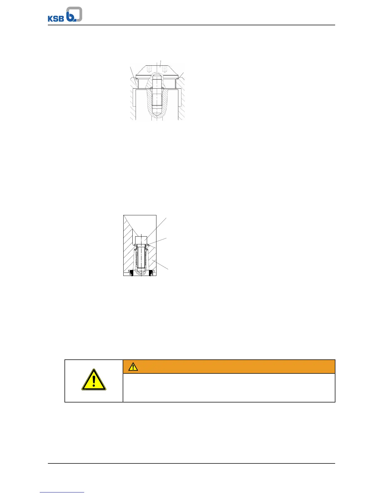
Fig.48: Fitting the impeller
ü The pre-assembly has been completed.
ü The assembled bearing bracket is placed in a suitable assembly area with the
pump end up.
ü Lifting equipment is provided.
1. Insert key 940.01 into the keyway.
2. Slip impeller 230 onto shaft 210.
3. Insert O-ring 412.03.
4. Screw in and tighten impeller screw 906.01.
7.5.6.4 Impeller with tapered interference fit
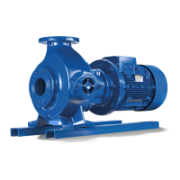
Fig.49: Fitting the impeller
ü The pre-assembly has been completed.
ü The assembled bearing bracket is placed in a suitable assembly area with the
pump end up.
ü Lifting equipment is provided.
1. Slip impeller 230 onto shaft 210.
2. Insert hexagon socket head cap screw 914.10 and disc 550.23, and tighten the
screw.
7.5.7 Installing the back pull-out unit
WARNING
Back pull-out unit tilting
Risk of crushing hands and feet!
▷ Suspend or support the bearing bracket at the pump end.
Version with wear plate (for D type impellers only)
ü The shaft, rolling element bearings, mechanical seal and impeller have been
assembled properly.
ü The pump casing is not connected to the piping.