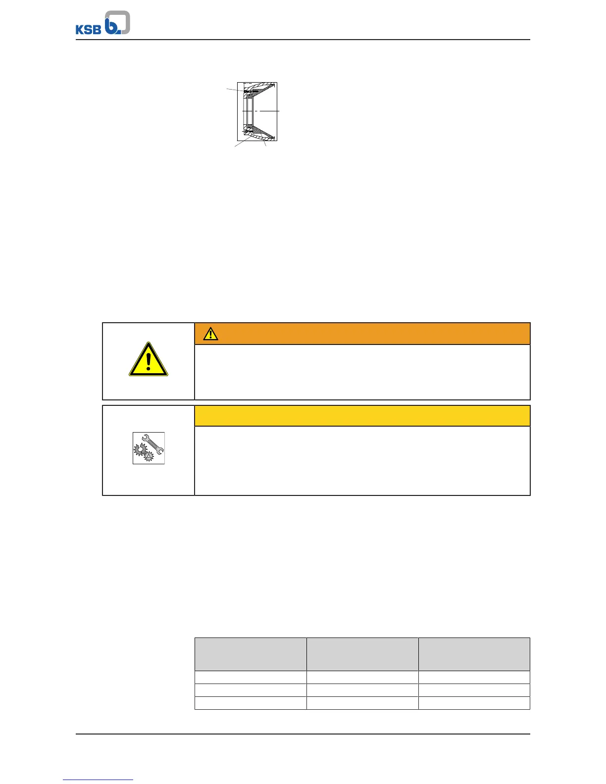
Fig.37: Removing the wear plate
ü The back pull-out unit, the belt drive (if any) and the motor have been properly
removed from the pump casing.
ü The inside of the casing has been cleaned.
ü The wear plate needs to be replaced as a result of visual inspection.
1. Unbolt the pump casing from the piping.
2. Undo hexagon socket head cap screws 914.12.
3. Remove wear plate 135.01 and O-rings 412.34.
7.5 Reassembling the pump set
7.5.1 General information/Safety regulations
WARNING
Improper lifting/moving of heavy assemblies or components
Personal injury and damage to property!
▷ Use suitable transport devices, lifting equipment and lifting tackle to move
heavy assemblies or components.
CAUTION
Improper reassembly
Damage to the pump!
▷ Reassemble the pump (set) in accordance with the general rules of sound
engineering practice.
▷ Use original spare parts only.
Sequence
Always reassemble the pump in accordance with the corresponding general assembly
drawing or exploded view.
Sealing elements
Check O-rings for any damage and replace by new O-rings, if required.
Never use O-rings that have been made by cutting an O-ring cord to size and gluing
the ends together.
Make sure that the sealing elements and sealing surfaces are clean.
Assembly adhesives
Coat the locating surfaces of the individual components and screwed connections
with graphite or similar before reassembly.
Tightening torques
For reassembly, tighten all screws and bolts as specified in this manual.
Bearings
Only use specified bearings to DIN628 (320.02) and DIN5412 (322.01).
Table22: Bearings
Bearing bracket size Angular contact ball
bearings
DIN628 (320.02)
Cylindrical roller bearing
DIN5412 (322.01)
S05 2x 7315 BG 8 NU 313
S06 2x 7319 BUA NU 416
S07 / S08 2x 7324 BUA NU 324

 Loading...