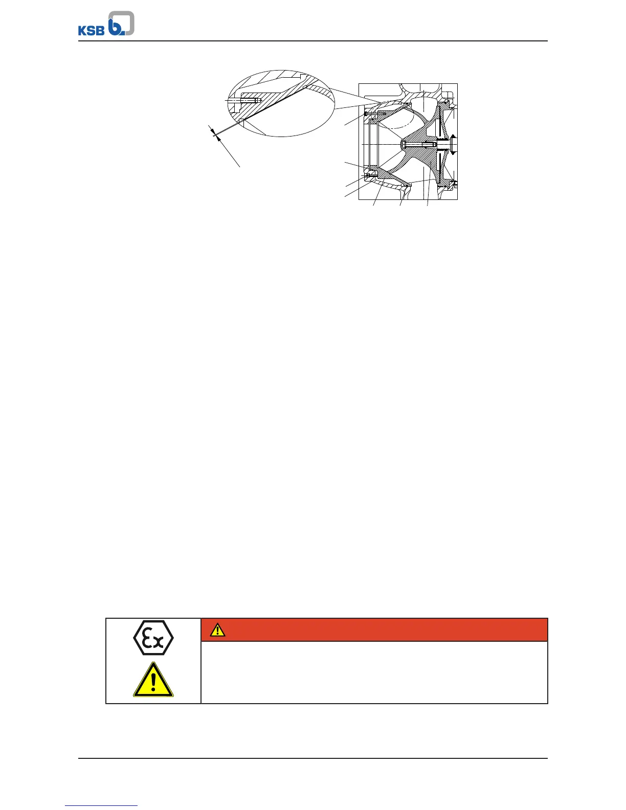
Fig.50: Fitting the wear plate
1. Equip wear plate 135 with two new O-rings 412.33 and 412.34.
2. Insert wear plate 135 into pump casing 101.
3. Fasten wear plate 135 to pump casing 101 with socket head cap screws 914.12.
4. Adjust the clearance between impeller 230 and wear plate 135 by loosening and
tightening screws 914.12 and 914.24.
ð Screw 914.24 presses the wear plate in the direction of the impeller.
ð The clearance equals 0.4
+0.2
mm (measured on the suction side from the
outer surface of the impeller vane to the wear plate).
5. Insert the complete back pull-out unit into the pump casing.
6. Evenly tighten screwed connection 920.01 between pump casing and bearing
bracket.
7. Fasten the support foot to the baseplate with bolts 901.61 and discs 550.61.
7.5.8 Leak test
7.5.8.1 Checking the mechanical seal for leakage
After reassembly of the pump, subject the mechanical seal area/lubricant reservoir to
a leak test.
1. Tightly screw the testing device into the filler opening (auxiliary connection
13D).
2. Test medium: compressed air
Test pressure: max. 0.8 bar
Test period: 2 min
ð The pressure must not drop during the test period.
ð If the pressure does drop, check the seals and screwed connections. Then
perform another leak test.
3. Once the leak test has been successful, fill in the lubricant.
7.5.8.2 Checking and adjusting the gland packing
DANGER
The temperatures at the gland packing have risen above the permissible limits
Explosion hazard!
▷ Gland packings are not approved for use in potentially explosive atmospheres.
▷ Immediately switch off the pump set!