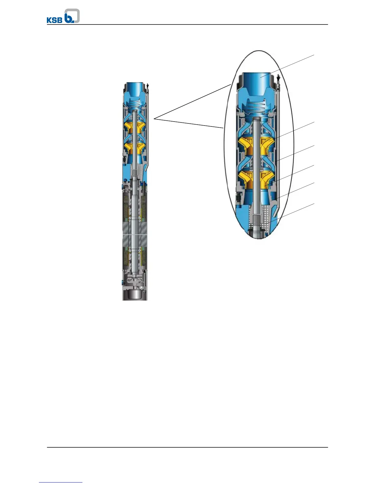
Fig. 3: Sectional drawing, example of a UPA
Pump and motor are connected by a rigid coupling. The stage casings are supported
by straps or stud bolts. A suction strainer at the suction casing protects the pump
from coarse particles in the fluid. The pump set is connected to the piping via a non-
return valve or connection branch with either internal thread or flanged end
(optional).
The fluid flows along the motor and enters the suction casing (2) through the suction
strainer (1). It is accelerated outward by the suction impeller (3). In the flow passage
of the stage casing (4) the kinetic energy of the fluid is converted into pressure
energy, and the fluid is routed to the next impeller (5). This process is repeated in all
stages until the fluid has passed the last impeller (5). It is then guided through the
integrated non-return valve to the connection branch (7), where it leaves the pump.
The integrated non-return valve prevents uncontrolled backflow of the fluid.
4.6 Scope of supply
Depending on the model, the following items are included in the scope of supply:
▪
Pump set with motor lead
Optional: pump and/or motor as individual units
Design
Function
4 Description of the Pump (Set)
18 of 64
UPA, UPZ, BSX