6. Transfer the core identification of the motor lead to the cores of the extension
cable. Make sure the colour codes match when connecting the cores.
The core codes depend on the wiring type of the motor:
Table 9: Core codes
Motors for DOL starting with 1 lead
U V W
.
Motors for DOL starting with 2 parallel leads
U1 - 1 V1 - 1 W1 - 1 U1 - 2 V1 - 2 W1 - 2
5.2.8 Measuring the insulation resistance
DANGER
Hazardous voltage during and after measurement
Danger of death from electric shock!
▷ Do not touch the contact points during and immediately after measurement.
▷ Insulation resistance measurement must be effected by a trained electrician
only.
Measure the insulation resistance prior to installation and prior to connection to the
power supply.
Insulation resistance measurement must be effected by a trained electrician only.
Prior to the measurement, ensure compliance with the operating instructions of the
device for measuring the insulation resistance.
✓ An insulation resistance measuring device with a measuring voltage of 1000 V DC
to 2500 VD C max. is available.
✓ The contact points are clean and dry.
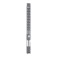
1.
Measurement period: 1 minute
9)
2.
Minimum insulation resistance at 20 °C - 30 °C: > 200 MOhm
1 lead 2 leads (parallel)
5.3 Installing the pump set in vertical position
NOTE
Observe all safety instructions contained in this manual for the following
installation instructions. (⇨ Section 5.1 Page 20
)
9)
The measured value must be steady; a longer measurement period might be needed for larger cable cross-sections.
5 Installation at Site
UPA, UPZ, BSX
27 of 64