Maximum permissible run-up and run-down times
The run-up process from standstill to the minimum frequency f
min
must not exceed 2
seconds. The run-down process must also take no more than 2 seconds.
Minimum frequency
Observe the following minimum frequencies.
Table 12: Minimum frequencies
Motor size Minimum frequency f
min
(Hz)
for vertical installation for horizontal installation
2-pole motors 20 30
4-pole motors 30 35
Maximum operating frequency
Do not exceed the maximum operating frequency of 50 Hz/60 Hz.
Winding load
Observe the following limits:
Maximum rate of voltage rise: du/dt ≤ 500 V/μs
Maximum voltage peaks against earth: 0.9 • U
N
NOTE
An output filter must be fitted to observe the limits.
Control principle of the frequency inverter
The control principle has to correspond with a linear U/f characteristic. If other
control principles are employed, such as field-oriented inverters, inverters with DTC
or NOF, the manufacturer of the frequency inverter must ensure that the special
features of submersible motors (very small moment of inertia, electrical data) are
taken into account.
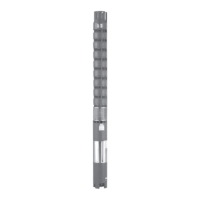
5.7 Electrical connection
DANGER
Work on the pump set by unqualified personnel
Danger of death from electric shock!
▷ Have cables terminated by qualified personnel only.
▷ Observe regulations IEC 30364 (DIN VDE 0100) and HD 637 S1 (DIN VDE 0101).
DANGER
Earth conductor not properly connected
Danger of death from electric shock!
▷ Never operate the motor without earth conductor.
▷ The earth conductor must be connected by a professional electrician only.
WARNING
Incorrect connection to the mains
Damage to the mains network, short circuit!
▷ Observe the technical specifications of the local energy supply companies.
1. Check the available mains voltage against the data on the name plate.
2.
Terminate the cable ends properly with suitable cable terminations. If cable
terminations are included in KSB's scope of supply, observe the separate
installation instructions.
3. Check the starting method in the data sheet and select the corresponding
circuit diagram.
5 Installation at Site
34 of 64
UPA, UPZ, BSX