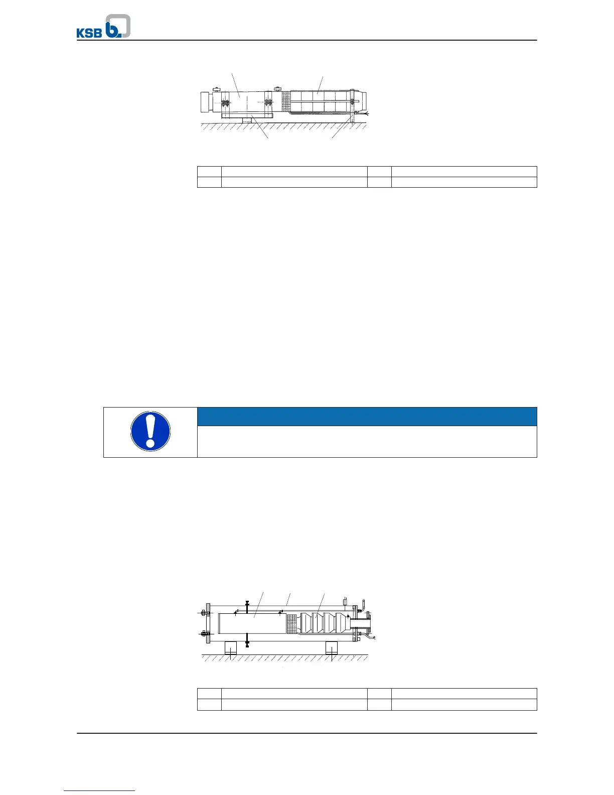
Fig. 6: Installation example with supporting frame and bearing pedestal
1 Motor 2 Pump
3 Supporting frame 4 Pedestal
Observe the following positions of the supporting frame and bearing pedestal:
Supporting frame for the motor: Mounting clamps at the casing flanges
Bearing pedestal for the pump: Last stage or non-return valve / connection branch.
✓ The structural dimensions have been verified.
✓ The water storage tanks have been installed.
✓ The motor fill has been checked and topped up, if required.
✓ Any extension cables have been connected to the power cable as well as to the
measuring and control cables.
1.
Undo the ties holding the cable guard. Remove the cable guard.
2. Fasten the supporting frame and bearing pedestals to the pump set. Position
and align the assembly on the foundation/floor.
3. Mark and drill the holes for the fixing bolts on the foundation and fasten the
pump set with the supporting frame/pedestals on the foundation.
4. Run the power cable through the foot of the pump bearing pedestal and fasten
it to the pump (approximately in the middle of the pump's overall length) and
the non-return valve / connection branch with cable ties.
Make sure the cable is securely fastened to prevent it from fluttering in the
water flow. Use a protective tube, if necessary!
NOTE
Fit an expansion joint between the piping and the pump set to prevent any piping
forces and vibrations from affecting the pump set.
5. Install the piping.
6.
Securely fasten the power cable as well as any measuring and control cable to
the piping with cable ties or use other suitable cable guides.
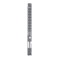
5.4.2 Installing the pump set in a suction, pressure or cooling shroud
For special operating conditions, submersible borehole pumps can be equipped with
a suction, pressure or cooling shroud; see order documentation or data sheet.
In such cases, always refer to the additional documentation supplied with the
delivery. See the operating instructions of the accessory "Suction, pressure or cooling
shroud".