13
ENGLISH
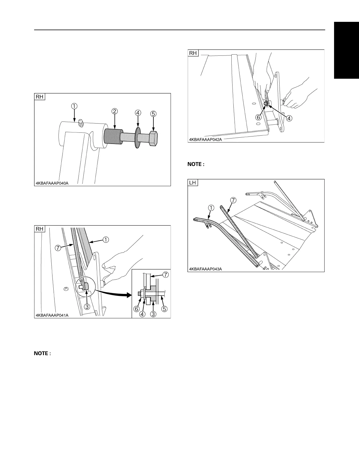
BASSEMBLE THE LIFT ARM LOWER RH
AND LH ASSY
1. Place the hex bolt (5) through the link collar (2) and the
plain washer (4) into the bottom side hole of the lower
lift arm (1).
2. Place the lower lift arm (1) to the frame. Insert the hex
bolt (5) from the frame side.
Place the lift arm collar (3) onto the hex bolt (5) and the
link plate (7).
3. Secure the lower lift arm (1) and the link plate (7) with
the hex bolt (5), the plain washer (4) and the locking
nut (6).
A Tightening torque: 77.4 to 90.2 N-m (7.9 to 9.2 kgf-m)
4. Do the same for the LH arm (1) and the link plate (7).
A Tightening torque: 77.4 to 90.2 N-m (7.9 to 9.2 kgf-m)

 Loading...