5
ENGLISH
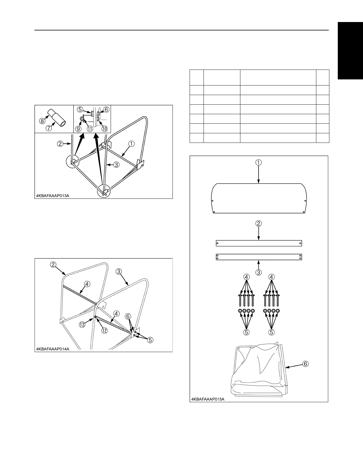
BASSEMBLE THE FRAMES
1. Place the bag frame LH (2) & RH (3) to the inside of
front bag frame (1). Secure each side by placing the
lock collar 2 (8) in the lock collar (7) and then insert the
flange bolt (9) through each frame and secure each
bolt with the plain washer (11) and the locking nut (10).
Place two flange bolts (5) and two flange nuts (6) in the
top hole.
2. Place the bag rod (4) to the bag frame LH (2) & RH (3)
(to the outside). Place a flange bolt (12) at the bottom
with the bag rod in the bottom hole and secure with a
flange nut (13), then secure the other side of the bag
rod (4) to the bag frame with two flange bolts (5) and
two flange nuts (6) in the direction as shown in the
figure. Do the same for the other bag rod (4).
[2]BAG ASSEMBLY
BPARTS LIST
Ref.
No.
Part Number Description Qty
(1) K6312-6361-2 PLATE, UPPER CORNER 1
(2) K6312-6362-0 PLATE, BOTTOM R 1
(3) K6312-6363-0 PLATE, BOTTOM F 1
(4) 01611-50635 BOLT, SQUARE NECK 8
(5) 02751-50060 NUT, FLANGE 8
(6) K6312-6354-2 NET, BAG 1
 Loading...