EasyManuals Logo

Kubota G23 Assembly Instructions

Kubota G23
124 pages
To Next Page IconTo Next Page
To Previous Page IconTo Previous Page
Page #9 background imageLoading...
Page #9 background image
7
ENGLISH
6. Place the bottom plate F (3) and R (2) to the bottom of
the bag, and secure them with square neck bolts (4)
and six flange nuts (5).
[3]HINGE ASSEMBLY
BPARTS LIST
Ref.
No.
Part Number Description Qty
(1) K6312-6348-3 PIN, HINGE LH 1
(2) K6312-6346-2 PIN, HINGE LEVER LH 1
(3) K6312-6349-2 PIN, HINGE RH 1
(4) K6312-6347-2 PIN, HINGE LEVER RH 1
(5) K5651-4467-0 SPRING, PIN 2
(6) 75599-52532 PIN, SPRING (7/32 x 1-5/8) 2
(7) 01754-50612 BOLT, FLANGE 4
(8) K1122-9181-0 NUT, SPRING (M8 x 1.25) 4

Table of Contents

Other manuals for Kubota G23

Questions and Answers:

Question and Answer IconNeed help?

Do you have a question about the Kubota G23 and is the answer not in the manual?
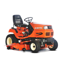
Kubota G23 Specifications

General IconGeneral
Engine Power23 HP
TransmissionHydrostatic
Cutting Width48 inches
Fuel TypeDiesel
Drive2WD
Number of Blades3
Engine TypeDiesel
Fuel Capacity6.3 gallons

Related product manuals