21
ENGLISH
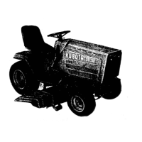
BASSEMBLE THE COVER DUCT
1. Place the rear duct cover (1) and the sensor stay assy
(2) to the front bag.
Hold the rear duct cover (1) with 2-35mm flange bolts
(4), and the sensor stay assy (2) below the duct with 2-
30mm flange bolts (5).
Then secure four flange bolts (4)(5) with four flange
nuts (6).
2. Hold the other side of duct with 2-35mm flange bolts
(4), and place 2-30mm flange bolts (5) into the sensor
stay assy (2). Then secure four flange bolts (4)(5) with
four flange nuts (6).
Place the sensor spring (3) as shown in the figure.
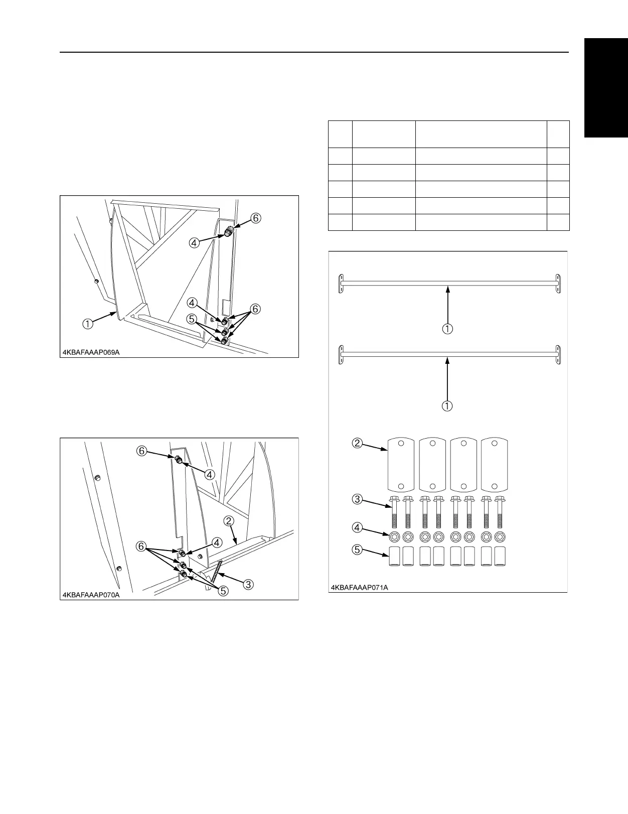
[9]JOINT, LIFT ARM ASSY
BPARTS LIST
Ref.
No.
Part Number Description Qty
(1) K6313-6429-2 JOINT, LIFT ARM 2
(2) K6313-6428-0 STAY, LIFT ARM 4
(3) 01754-50840 BOLT, FLANGE 8
(4) 02751-50080 NUT, FLANGE 8
(5) K6313-6427-0 COLLAR, JOINT 8

 Loading...