EasyManuals Logo

Kubota G23 Assembly Instructions

Kubota G23
124 pages
To Next Page IconTo Next Page
To Previous Page IconTo Previous Page
Page #13 background imageLoading...
Page #13 background image
11
ENGLISH
<High Dump>
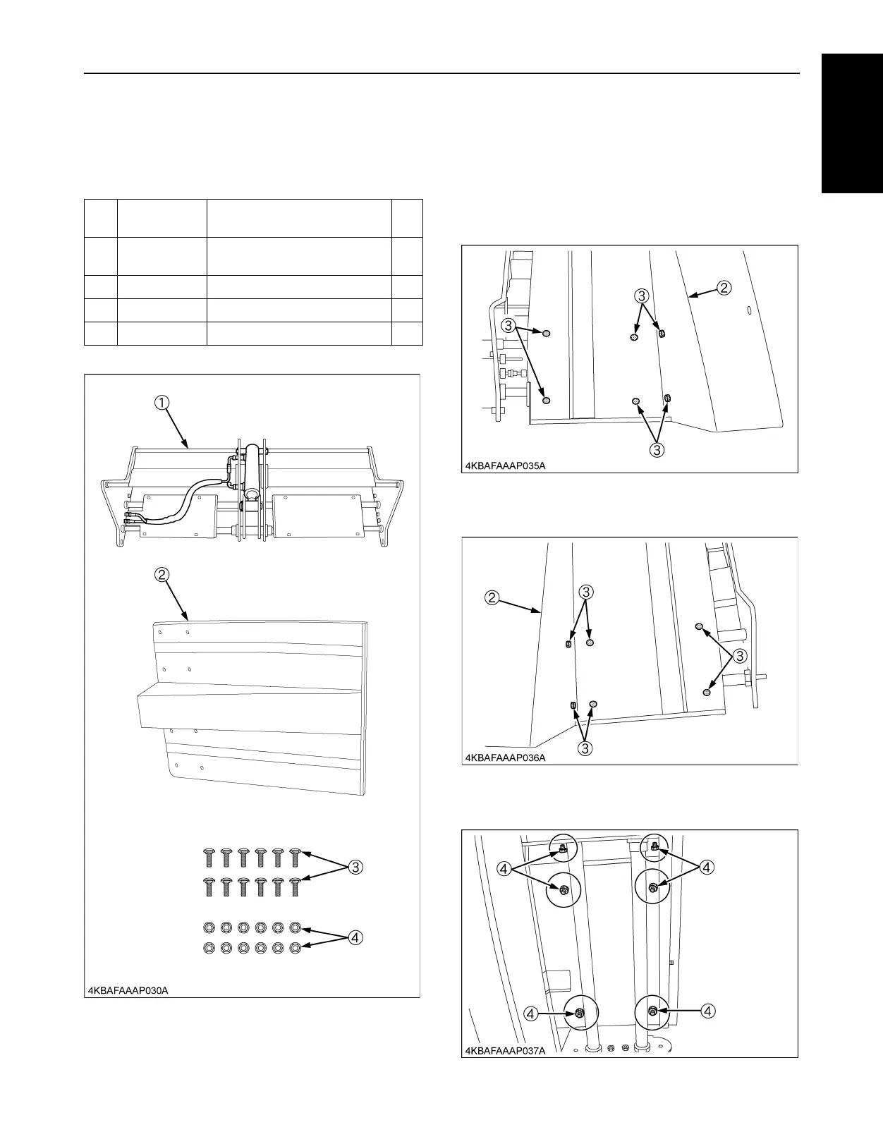
[1]CONNECTION, COMP.LIFT ARM ASSY
BPARTS LIST
BASSEMBLE THE CONNECTION,
COMP.LIFT ARM ASSY
1. Place the bottom plate (2) over the cylinder as shown
in the figure.
Secure the right side with six short square neck bolts
(3).
2. Secure the left side with six short square neck bolts
(3).
3. Secure six short square neck bolts (3) on the left hand
side with six flange nuts (4).
Ref.
No.
Part Number Description Qty
(1) -
CONNECTER, COMP.LIFT
ARM
1
(2) K6313-6375-3 PLATE, BOTTOM 1
(3) K1122-9132-0 BOLT, SHORT SQU.NECK (M8) 12
(4) 02751-50080 NUT, FLANGE 12

Table of Contents

Other manuals for Kubota G23

Questions and Answers:

Question and Answer IconNeed help?

Do you have a question about the Kubota G23 and is the answer not in the manual?

Kubota G23 Specifications

General IconGeneral
Engine Power23 HP
TransmissionHydrostatic
Cutting Width48 inches
Fuel TypeDiesel
Drive2WD
Number of Blades3
Engine TypeDiesel
Fuel Capacity6.3 gallons

Related product manuals