5.4 Replacing the PCBs and Fuses
The main and RF PCBs are protected by a cover fastened to the
antenna support frame. This cover must be removed to gain
access to the PCBs and fuses discussed in the following sections.
Removing the PCB Cover
1. Using a
3
⁄8" nut driver/socket, remove the three
nuts and washers from the PCB cover’s bottom
flange.
2. Remove the three Phillips screws and washers
from the PCB cover’s upper flange.
3. Remove the PCB cover and set aside.
54-0161
108
TracVision G6 Technical Manual
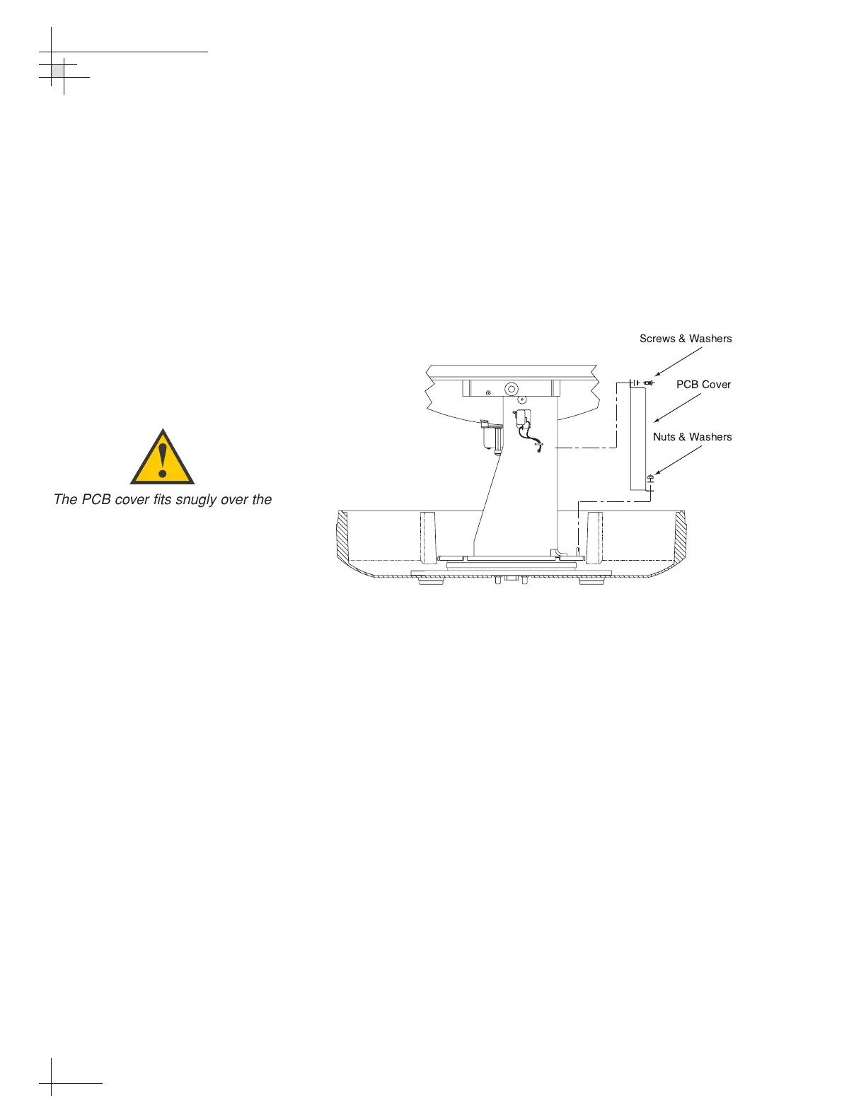
Figure 5-2
PCB Cover Removal
The PCB cover fits snugly over the
PCBs. When removing or replacing
the cover, take care to ensure that
the cover does not dislodge any of
the Molex connectors, as this will
cause system errors and improper
operation.
 Loading...


