5.5 Replacing the Antenna Gyro
Assembly
1. Remove the PCB cover, as explained in “Removing
the PCB Cover” on page 108.
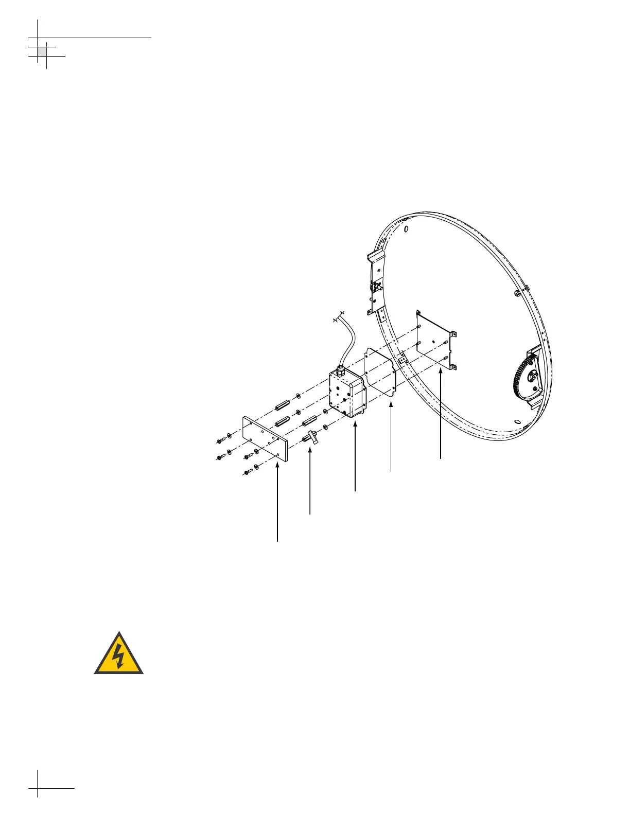
2. Remove the four screws, four washers, and the
counterweight from the end of the antenna gyro
(see Figure 5-6).
3. Using a
3
⁄8" nut driver/socket, remove the four
standoffs securing the antenna gyro to the reflector
bracket (see Figure 5-6). Slide the tie-wrap, which
secures the antenna gyro cable, off the bottom
right standoff.
4. Remove the 3 tie-wraps securing the gyro cable to
the RF cables (see Figure 5-1 on page 107).
5. Disconnect the antenna gyro Molex connector
from the main PCB (see Figure 5-3 on page 109).
Remove the old antenna gyro assembly.
54-0161
112
TracVision G6 Technical Manual
Make sure the cable jacket passes
through the PCB access slot to
protect the wires from the edge of
the PCB frame.
 Loading...


