2.6 Wiring the ADCU
All other wiring for the TracVision system connects at the rear
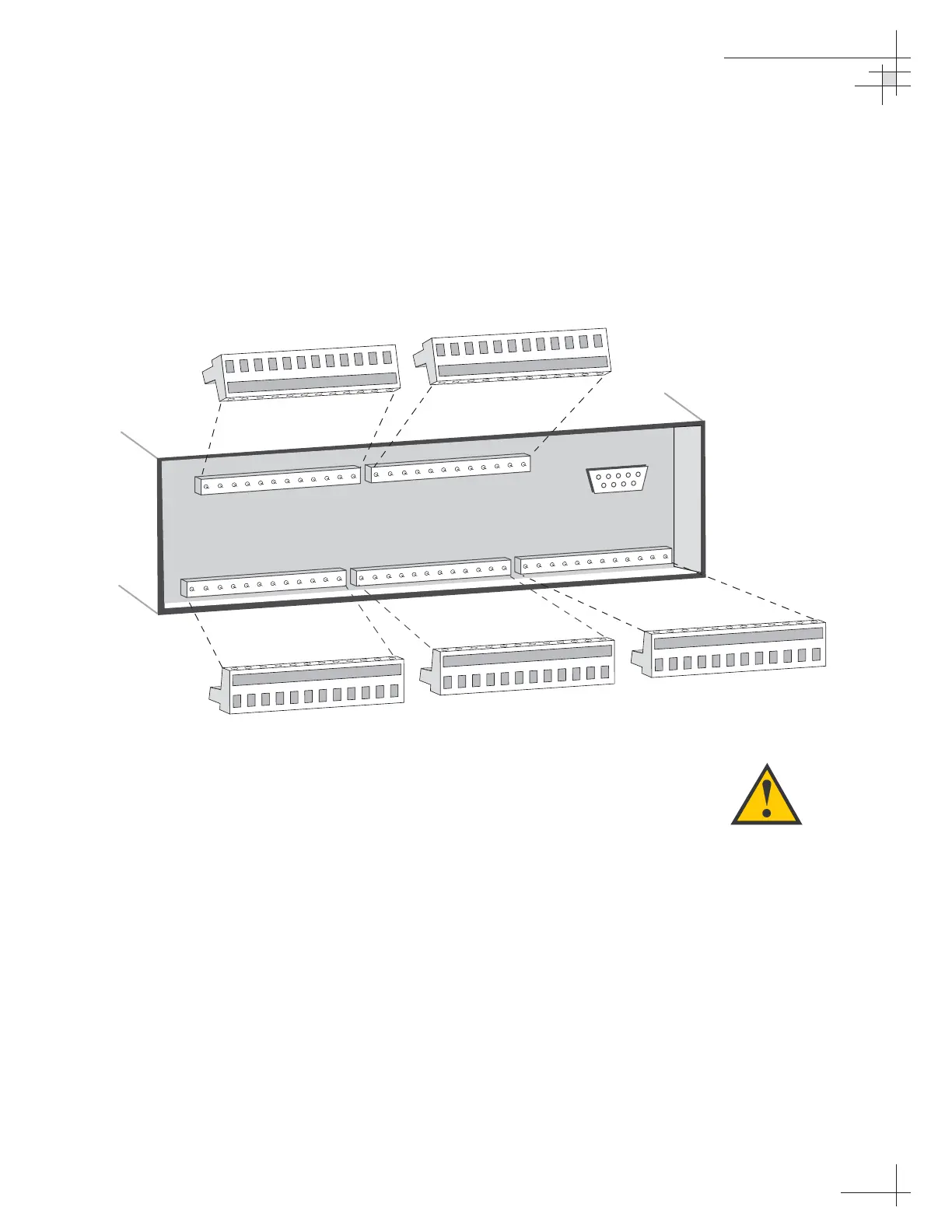
panel of the ADCU. Included in the GyroTrac kitpack are five
terminal strip connectors with terminal connectors numbered 1
through 60 (see Figure 2-20). You will connect all wires to these
terminal strip connectors first, then you will insert the connectors
into the rear panel of the ADCU.
For the TracVision system to work, you must connect the
following cables to the ADCU:
• Antenna Data Cable
• Antenna Power Cable (unless you are connecting
antenna power to its own circuit)
• GyroTrac Sensor Cable
• Vessel Power Cable
• IRD Ground Cable(s)
You may also connect other external devices, such as an
autopilot, plotter, remote display, or GPS.
Figure 2-21 on the following page shows all available connections
to the ADCU.
Installation
54-0161
31
Figure 2-20
Terminal Strip Connectors
Connect all wires to the terminal
strip connectors first.
DO NOT
attach the terminal strip connectors
to the ADCU until you have
completed and verified all wiring.
 Loading...


