6. Remove the foam shipping restraints from the
antenna unit.
7. Place the foam seal in position on the mounting
surface with the hole centered over the cable
access cutout. Do not remove the paper backing at
this time. Scribe a line all around the seal.
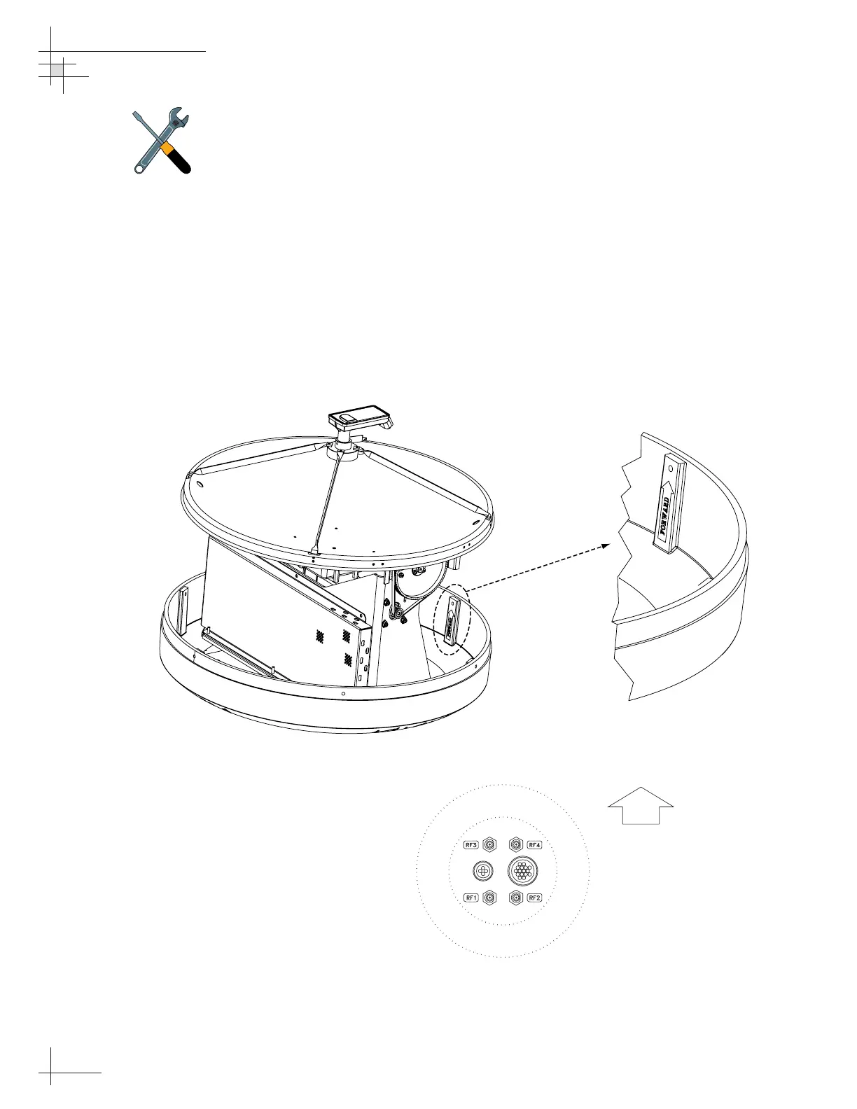
8. Position the baseplate assembly in place over the
mounting holes and cable access, with the
baseplate’s “Forward” arrow (shown in Figure 2-4)
pointing toward the bow. Ensure that all holes line
up and that the connectors are centered over the
cable access as shown in Figure 2-5. Make any
necessary adjustments before seating the foam seal
in place permanently.
54-0161
16
TracVision G6 Technical Manual
Figure 2-4
Baseplate “Forward” Arrow
Figure 2-5
Baseplate/Foam Seal Orientation
(Bottom View)
The foam shipping restraints must
be removed before power is
applied. Save the restraints for
reuse and be sure to install them
whenever the antenna unit is
moved from place to place. See
Section 5.10, “Preparing for
Shipment” on page 122
for details.
 Loading...


