Tips for Safe and Successful Wiring
• When inserting a wire into the terminal connector,
make certain that the wire insulation is not
pinched in the connector.
• After inserting and securing wire, tug gently to
ensure that the connection is solid.
• Position cables behind the ADCU so that they
connect neatly to the terminal strips.
• Do not tin (solder) the wire ends.
• Each cable provided with the TracVision G6
should be routed and dressed before terminating
at the ADCU. The antenna data and power cable
wires may be trimmed to desired length. However,
be sure to cut back the drain wire (shield); do
NOT connect the drain wire to anything.
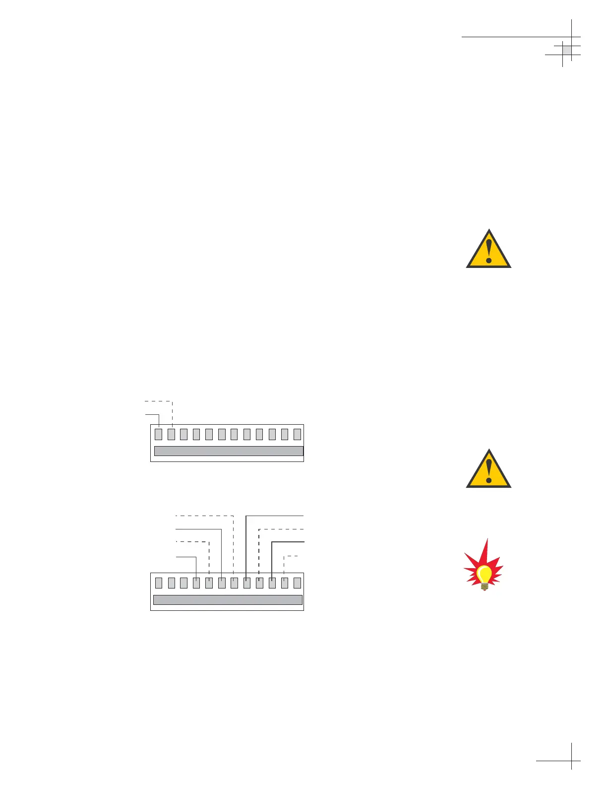
Connecting the Antenna Data Cable
Connect the antenna data cable to the red and yellow ADCU
terminal strip connectors as shown in Figure 2-22.
Installation
54-0161
33
A comprehensive wiring diagram of
the entire TracVision G6 system
has been provided for technical
reference in
Appendix C on
page 133
.
A color quick reference
guide to wiring your
TracVision G6 is also provided
on the inside front cover of this
manual.
Figure 2-22
Antenna Data Cable
to ADCU Wiring
Cut back any unused wires from
the Data Cable.
 Loading...


