EasyManuals Logo

KVH Industries TracVision G6 User Manual

KVH Industries TracVision G6
161 pages
To Next Page IconTo Next Page
To Previous Page IconTo Previous Page
Page #117 background imageLoading...
Page #117 background image
8. Route the new limit switch wires through the
cover and cable clamp to the main PCB’s Molex
connector. After noting the position of the old
black and white wires, remove the old wires from
the Molex connector. Attach the new wires in their
places.
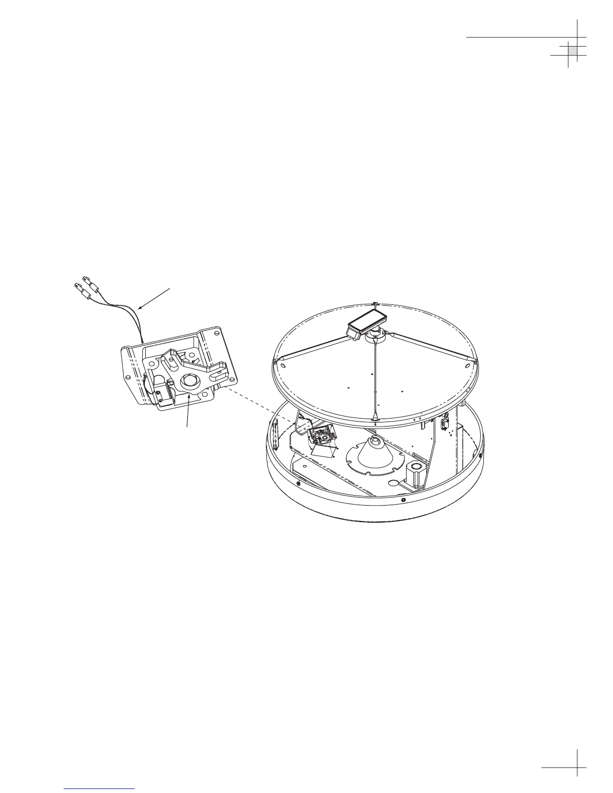
9. Before re-installing the azimuth limit switch to the
antenna assembly, orient the switch’s plastic cam
as shown in Figure 5-8. With the cam in the proper
position, reinstall the switch to the antenna
assembly using the three #6-32 retaining screws
and flat washers. Ensure the cam finger engages
the stop pin in the mounting cavity.
10. Apply hot melt or RTV at the limit switch cover’s
wire access hole to protect the wires from chafing.
Maintenance
54-0161
113
Plastic Cam
Black and White Wires
to Main PCB Molex Connector
Figure 5-8
Azimuth Limit Switch Orientation

Table of Contents

Other manuals for KVH Industries TracVision G6

Questions and Answers:

Question and Answer IconNeed help?

Do you have a question about the KVH Industries TracVision G6 and is the answer not in the manual?

KVH Industries TracVision G6 Specifications

General IconGeneral
BrandKVH Industries
ModelTracVision G6
CategorySatellite TV System
LanguageEnglish

Related product manuals