2.2 Mounting the TracVision
Antenna
1. Make sure that you have chosen a suitable
mounting location based upon the guidelines in
“Choosing the Best Location for the TracVision
Antenna” on page 12.
2. Remove the antenna unit from its shipping carton
and set the radome aside in a safe place.
3. Remove the foam shipping restraints from the
antenna unit.
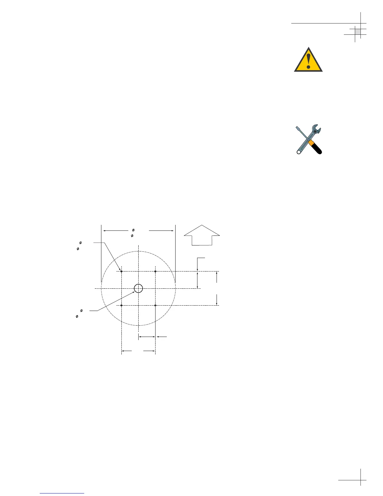
4. Using the template provided at the back of this
manual or the dimensions shown in Figure 2-3, lay
out the four mounting bolt holes and cable access
hole at the mounting site. Make certain that the
Forward arrow is parallel with the vessel’s
centerline and pointed toward the bow.
5. Drill the four
1
⁄2" (13 mm) bolt holes and cut out the
3" (80 mm) diameter cable access hole (following
the layout in Step 4). Smooth the edges of the cable
access hole to protect the cables.
Installation
54-0161
15
The foam shipping restraints must
be removed before power is
applied. Save the foam pieces for
reuse.
Be careful not to strike the exposed
connectors extending from the
bottom of the baseplate or allow
them to carry the weight of the
antenna unit.
Figure 2-3
Antenna Mounting Holes Layout
 Loading...


