2.10 Setting the Skew Angle
(European Systems Only)
To optimize channel reception, the antenna LNB skew angle must
be adjusted. Refer to your satellite service provider for the proper
skew angle for the selected satellite service and geographical
location. You can also find the proper skew angle from the
ADCU, as long as a GPS is providing data to the ADCU or the
vessel’s correct latitude and longitude are entered into the
ADCU. Refer to “Antenna Status Data Screens” on page 80 for
details on viewing the ADCU-calculated skew value.
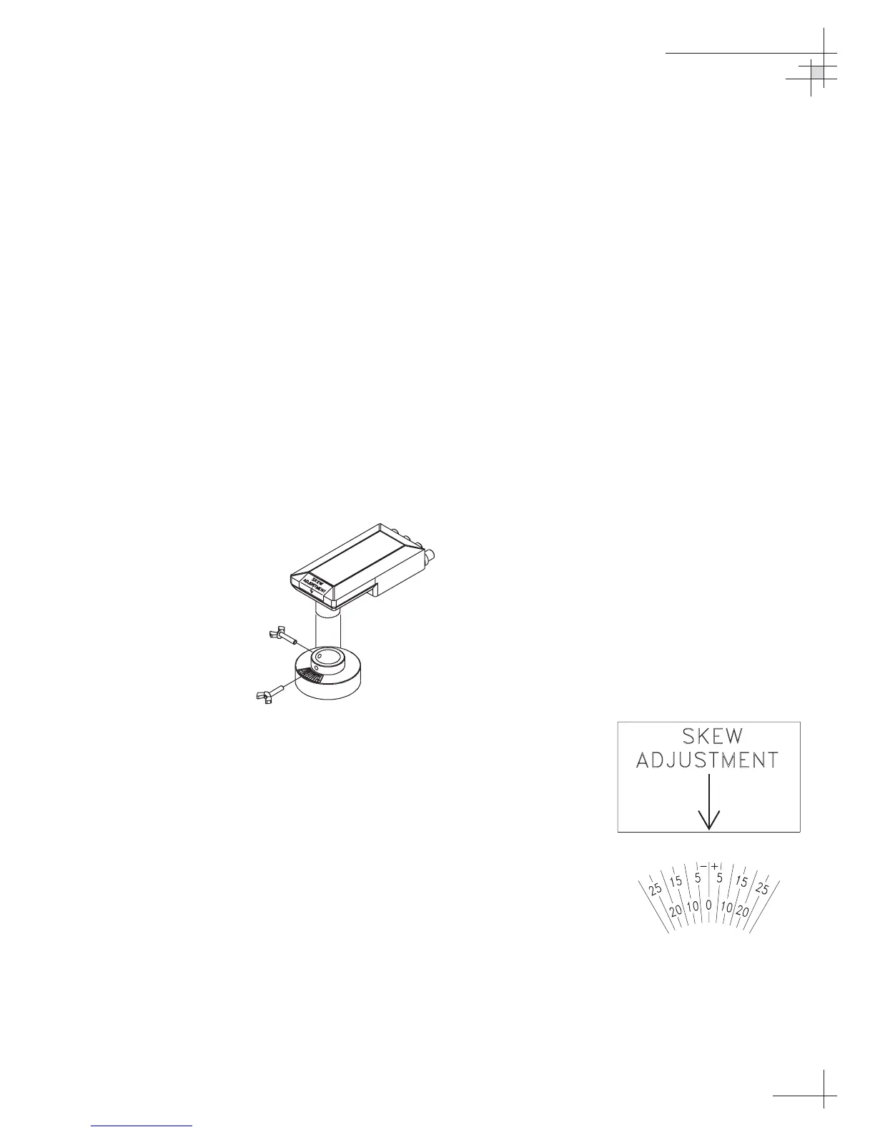
Adjusting the LNB Skew Angle
1. Turn off the power to the antenna unit.
2. Remove the radome and set it aside in a safe place.
3. Loosen the two wing screws securing the LNB
within the choke feed as illustrated in Figure 2-37.
4. Refer to the LNB skew angle labels on the end of
the LNB and on the LNB choke feed (pictured in
Figure 2-38) and adjust the LNB as necessary to
match as closely as possible the skew angle
provided by your service provider or the ADCU.
5. Retighten the wing screws.
6. Reinstall the radome. Align the six radome screw
holes with the inserts in the baseplate, insert the
screws and tighten. Install a protective plastic
screw cap over each screw.
Installation
54-0161
55
Figure 2-38
Skew Angle Labels
Figure 2-37
Adjusting the European
LNB Skew Angle
(Dual-output LNB)
 Loading...


