5.6 Azimuth Limit Switch Assembly
1. Rotate the antenna assembly, by hand, clockwise
until it stops.
2. Remove the PCB cover as explained in “Removing
the PCB Cover” on page 106.
3. At the main PCB, cut the black and white wires
from the azimuth limit switch Molex connector
(see Figure 5-3). Leave about an inch of the wires
still connected at the Molex connector for later
reference.
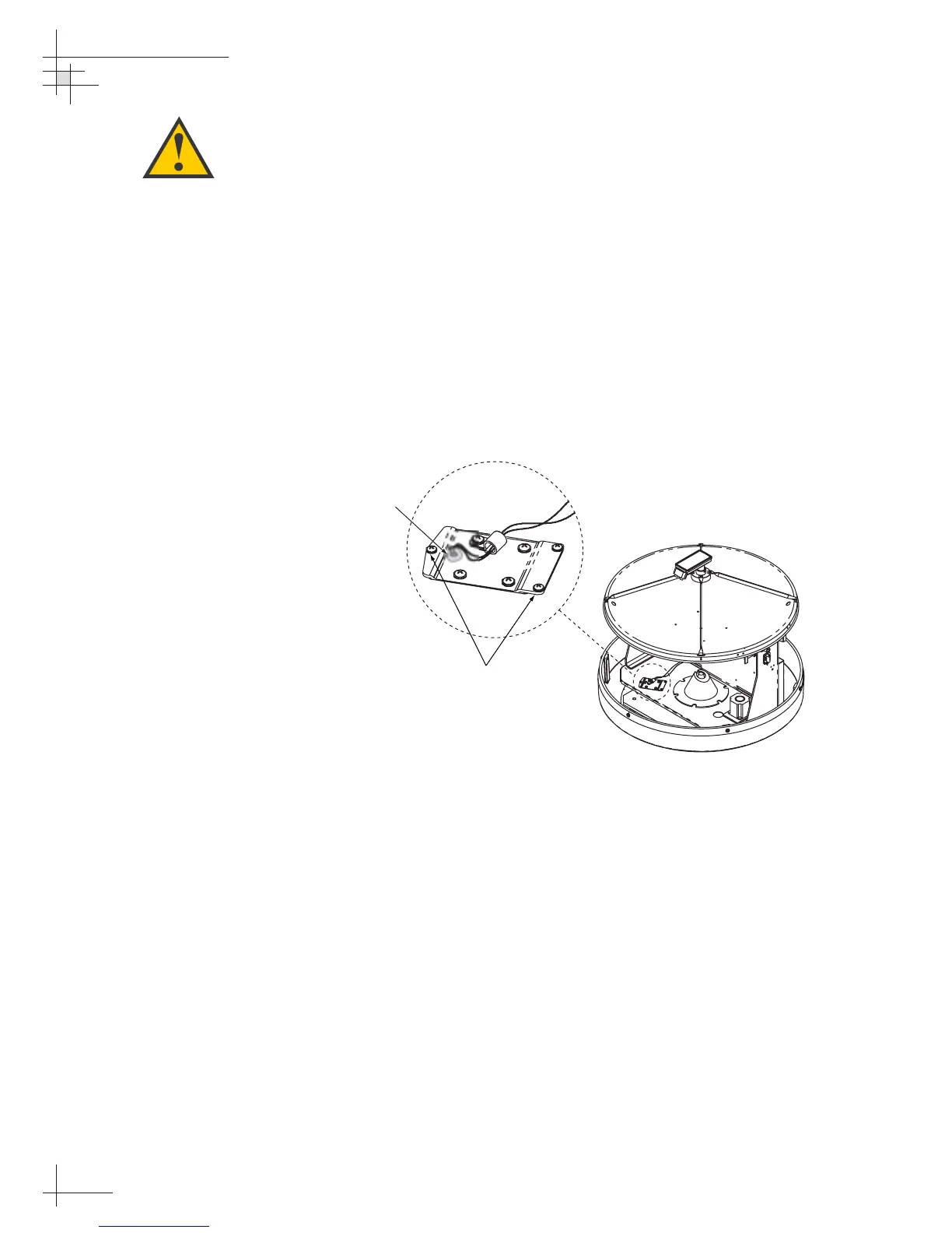
4. At the azimuth limit switch cover, remove the hot
melt holding the black and white wires in place
(see Figure 5-7).
5. Remove the three #6-32 retaining screws from the
limit switch cover and set aside (see
Figure 5-7). Lift the cover to access the limit switch
underneath.
6. Remove the four #8-32 screws securing the limit
switch to the cover and set aside.
7. Replace the azimuth limit switch. Attach the new
switch to the cover using the #8-32 screws, flat
washers, and cable clamp.
54-0161
112
TracVision G6 Technical Manual
Figure 5-7
Azimuth Limit Switch Cover
When rotating the antenna by
hand, go slowly! Hitting the
mechanical stops with excessive
force will damage the azimuth limit
switch.
 Loading...


