2DA/2DB
1-3-27
15. Fit the pin located at the left rear side of the
intermediate tray from the rear side of the
MFP onto the hook of the transfer unit.
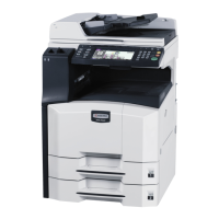
16. Remove the tape and pull out the 13-pin
connector and 24-pin connector.
Figure 1-3-47
17. Connect the 24-pin connector of the inter-
mediate tray to the connector of the transfer
unit.
18. Connect the 13-pin connector of the inter-
mediate tray to YC5 on the engine circuit
board.
Figure 1-3-48
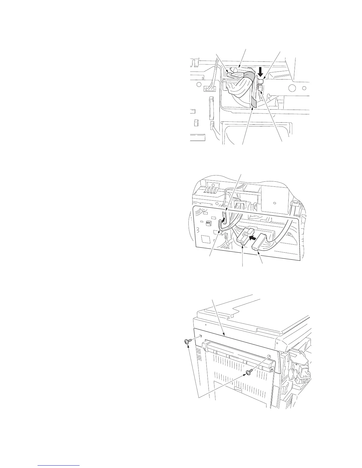
Attach the covers.
19. Attach the cover that has been removed by
Procedure 8 to its original position using the
two screws.
20. Attach the large ejection cover with the two
screws that have been removed by Proce-
dure 1.
Figure 1-3-49
Tap e
Hook
Pin
24-pin connector
13-pin connector
13-pin connector
Connector
24-pin connector
YC5
Screws
Large ejection cover

 Loading...