2DA/2DB
1-3-37
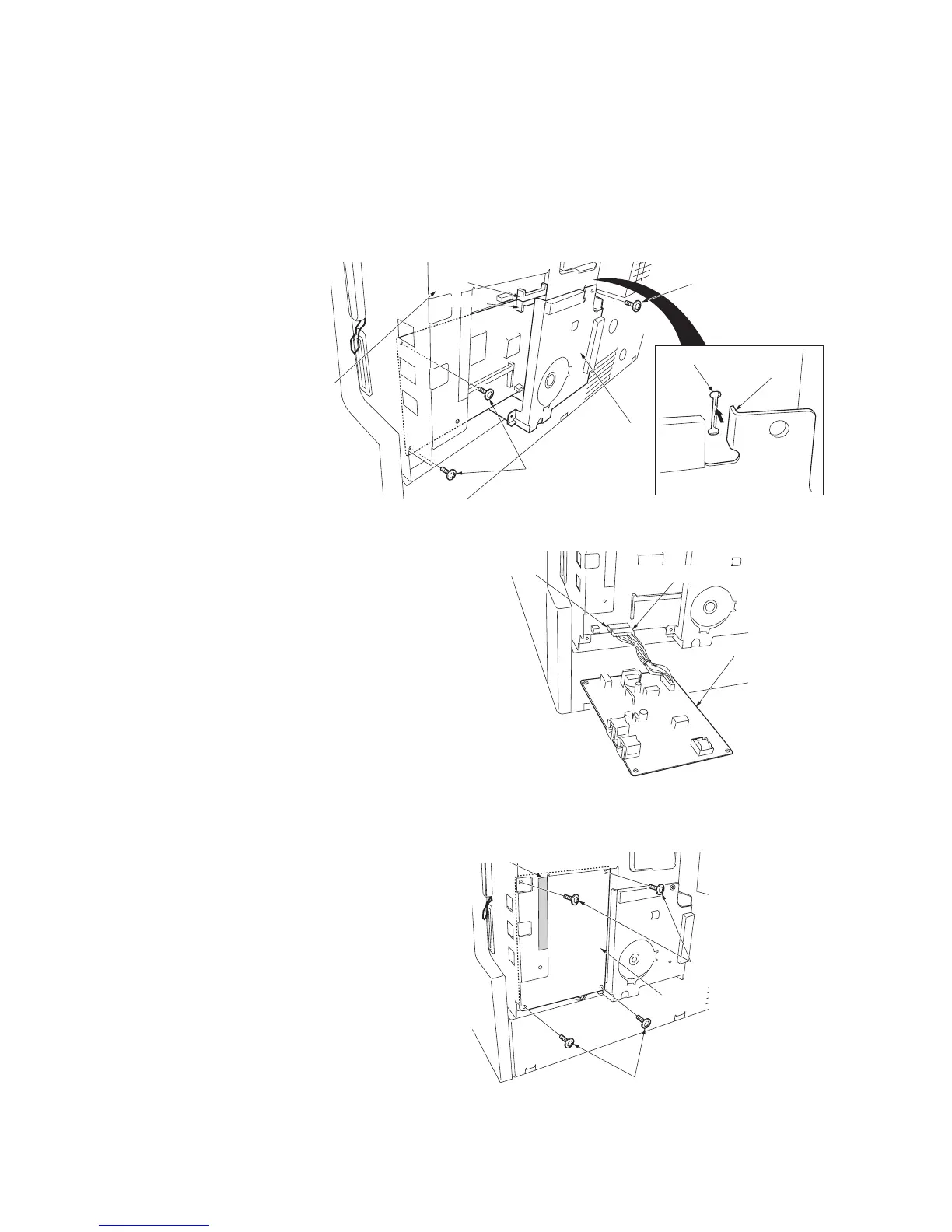
11. Connect the YC1 connector on the fax control PCB assembly to
the YC15 connector on the engine PCB.
12. Insert the fax control PCB assembly to the shield box so that the
projection of the fax control PCB assembly is positioned to the slit
of the shield box.
13. Secure the fax control PCB assembly using the three TP tap tight
screws M3 x 6.
Take care that the ground wire is not put on the frame section of
the rear cover.
Figure 1-3-70
Attach the NCU PCB assembly.
14. Connect the NCU wire connector on the
NCU PCB assembly to the YC2 connector
on the fax control PCB assembly.
Figure 1-3-71
15. Secure the NCU PCB assembly using the
four TP tap tight screws M3 x 6, paying
attention so that the tape section of the
shield box does not contact with the PCB.
Figure 1-3-72
YC1
YC15
Fax control
PCB assembly
Slit
Projection
TP tap tight
screws M3 x 6
TP tap tight screw M3 x 6
Shield box
Connector
Connector
YC2
NCU PCB assembly
NCU wire connector
Connector
TP tap tight screws M3 x 6
Tape section
TP tap tight screws M3 x 6
NCU PCB assembly

 Loading...