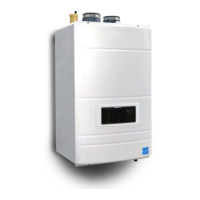
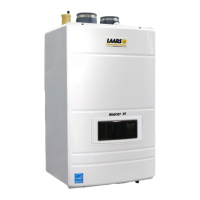
The FT Series Floor Standing, Combination Boiler
Page 31
WARNING:
Open ame can cause gas to ignite and result in
property damage, severe injury, or loss of life.
NOTE: The FT appliance and all other gas appliances
sharing the gas supply line must be ring at maximum
capacity to properly measure the inlet supply pressure.
The pressure can be measured at the supply pressure
port on the gas valve. Low gas pressure could be an
indication of an undersized gas meter, undersized gas
supply lines and/or an obstructed gas supply line.
SCHED 40 METAL PIPE CAPACITY FOR 1.50 SPECIFIC GRAVITY
UNDILUTED PROPANE
NOMINAL PIPE SIZE @ 11" W.C. INLET AND 0.5" W.C. PRESSURE DROP
SIZE 1/2" 3/4" 1"
LENGTH MAXIMUM CAPACITY IN THOUSANDS OF BTU PER
HOUR
20 200 418 787
40 137 287 541
60 - 231 434
80 - 197 372
100 - 175 330
NOTES: 1. Follow all local and national propane gas codes for line sizing and
equipment requirements. 2. Verify that inlet gas pressure remains between
4 and 13 inches of water column before and during operation.
Source: ANSI Z223.1-80 National Fuel Gas Code.
Table 6. Nominal Pipe Size, Propane
SCH 40 METAL PIPE CAPACITY FOR 0.60 SPECIFIC GRAVITY NATURAL GAS
NOMINAL PIPE SIZE @ 0.30" W.C. PRESSURE DROP
LENGTH 3/4" 1"
FT CUBIC FEET OF GAS PER HOUR
20 190 350
40 130 245
60 105 195
80 90 170
100
Table 7. Nominal Pipe Size, Natural Gas
4.9 Gas Supply and Piping
Gas piping should be supported by suitable hangers or
oor stands, not the appliance.
Review the following instructions before proceeding with
the installation.
1. Verify that the appliance is tted for the proper type
of gas by checking the rating plate. FT will function
properly at elevations up to 10,000 feet
(3050 m). Refer to Section 4.12 for High Altitude
Settings.
2. For minimum and maximum gas supply pressures.
See Section 2.2 on page 6
3. Refer to Table 6, Table 7, and Table 8 to size piping.
4. Run gas supply line in accordance with all
applicable codes.
5. Locate and install manual shuto valves in
accordance with state and local requirements.
6. A sediment trap must be provided upstream of the
gas controls.
7. All threaded joints should be coated with piping
compound resistant to action of liqueed petroleum
gas.
8. The appliance and its individual shuto valve
must be disconnected from the gas supply piping
during any pressure testing of that system at test
pressures in excess of 1/2 PSIG (3.45kPa).
9. The unit must be isolated from the gas supply
system by closing its individual manual shuto valve
during any pressure testing of the gas supply piping
system at test pressures equal to or less than 1/2
PSIG (3.45kPa).
10. The appliance and its gas connection must be leak
tested before placing it in operation.
11. Purge all air from gas lines.
EQUIVALENT LENGTHS OF STRAIGHT PIPE FOR TYPICAL SCH 40 FITTINGS
NOMINAL PIPE SIZE
FITTING 1/2" 3/4" 1"
LINEAR FEET
90° ELBOW 3.6 4.4 5.2
TEE 4.2 5.3 6.6
Table 8. Equivalent Pipe Lengths
CAUTION
PRV (included) must be installed immediately at the
top of boiler outlet to PRV, with no valves between.
Refer to Section 4.15
__________________________________________
ATTENTION
PRV (inclus) doit être installé immédiatement en haut
de la chaudière sortie de PRV, sans les vannes entre.
Se reporter à la Section 4.15
__________________________________________