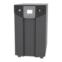
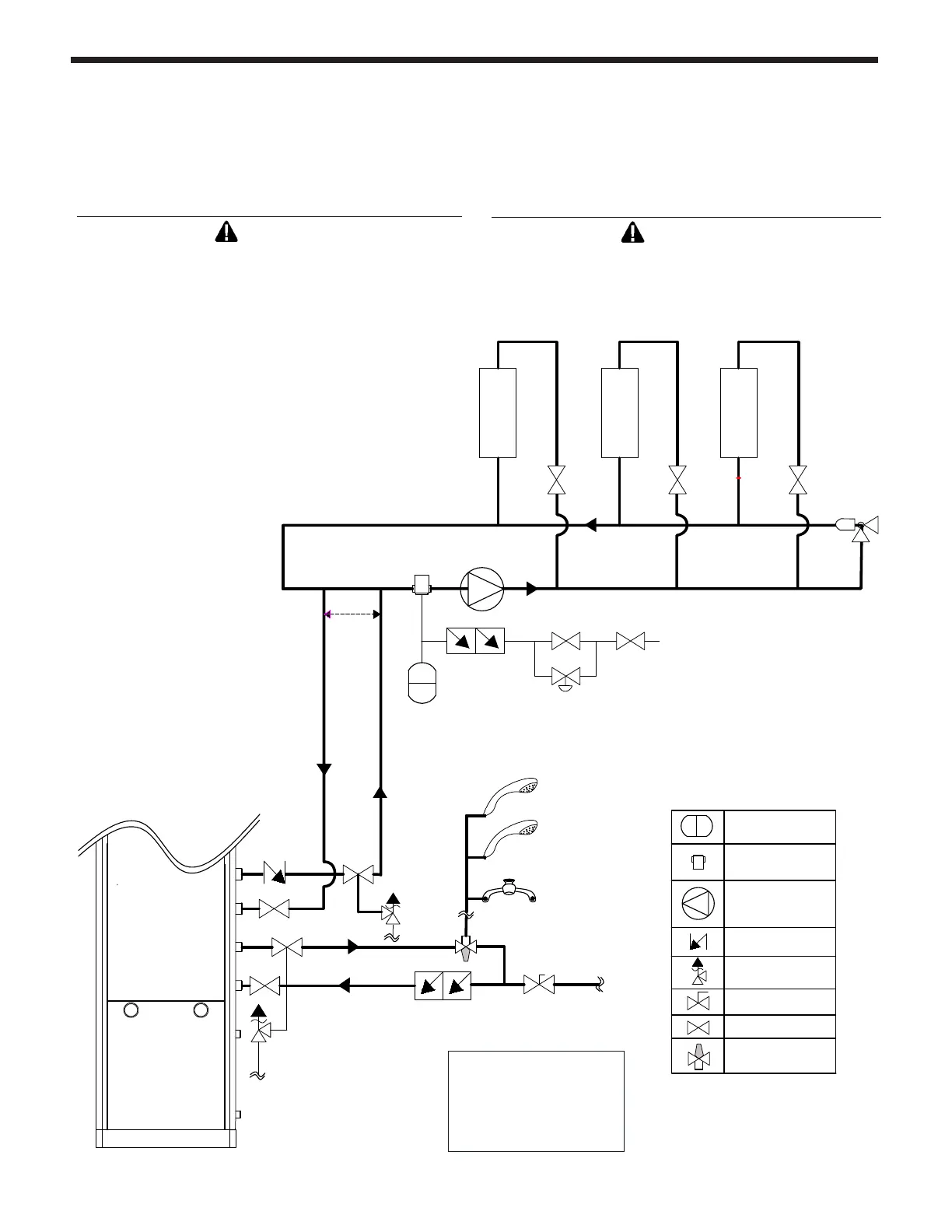
The FT Series Floor Standing, Combination Boiler
Page 45
(CH SUPPLY)
3/4" PIPE
(DHW OUTLET)
Backflow
preventer
3/4" PIPE
(DHW INLET)
(CH RETURN)
(DHW SUPPLY)
Circulation pump
Flow Check valve
Expansion tank
Air separator
Diaphragm Type
Pressure relief valve
Ball valve
Isolation valve
PRIMARY LOOP
(SPACE HEATING)
1”
Min
Piping
P
Make-Up Water
ZONE 1
ZONE 2
ZONE 3
Do not
exceed
12"
See
Note
SECONDARY LOOP
(SPACE HEATING)
Anti-scald rated
Mixing Valve
CAUTION
PRV (included) must be installed immediately at the
top of boiler outlet to PRV, with no valves between.
Refer to Section 4.15
__________________________________________
ATTENTION
PRV (inclus) doit être installé immédiatement en haut
de la chaudière sortie de PRV, sans les vannes entre.
Se reporter à la Section 4.15
__________________________________________
Auto Fill Valve
and Backow
Preventer Valves are
NOT included (Field
Supplied).
4.14.6 Zoning with Zone Valves
- In a valve based system, there is one circulator pump at the boiler and each heating zone has its own valve.
- Each thermostat is wired directly to the corresponding zone valve. Contacts in the zone valves provide a
proper signal to the boiler when the valve is opened.