Page 6
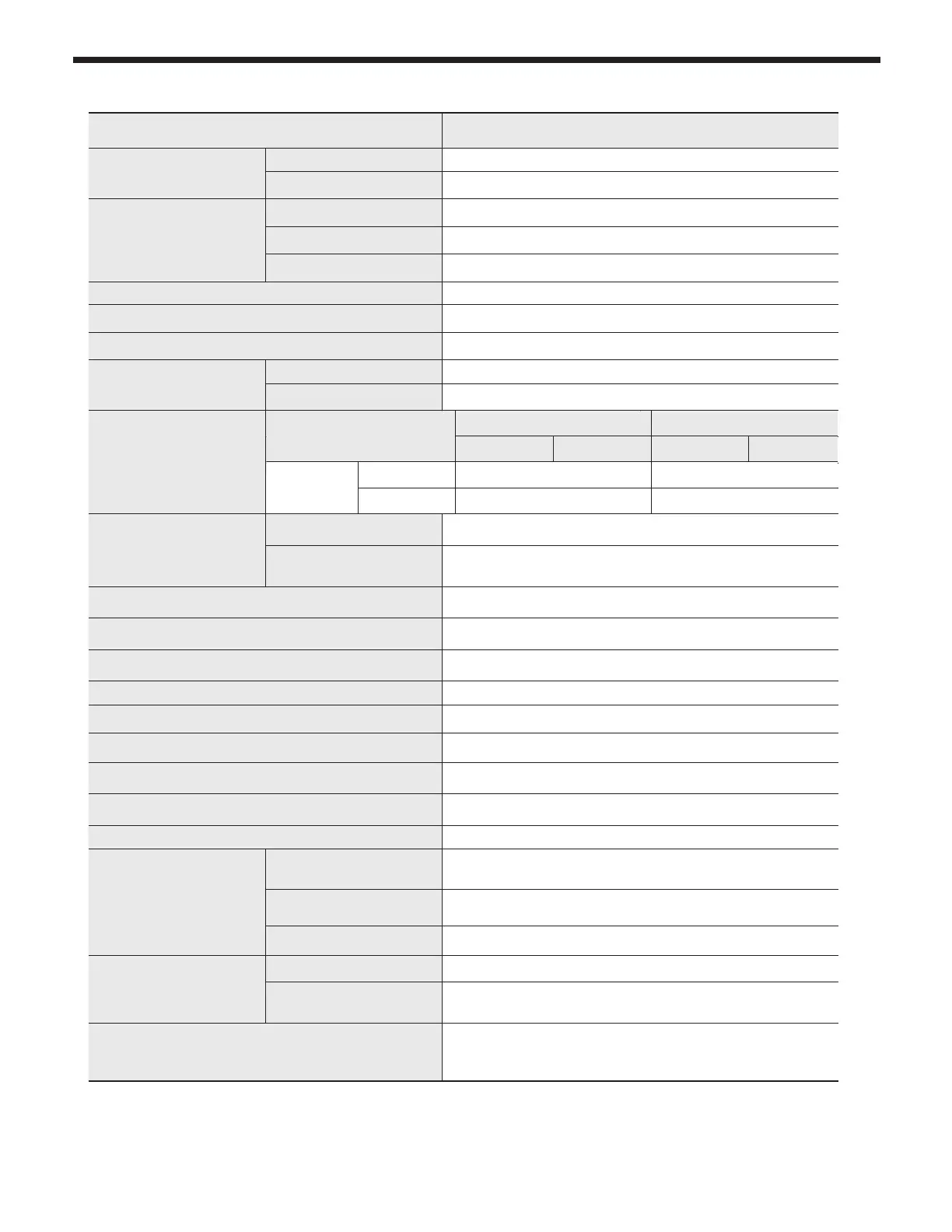
2.2 Specications
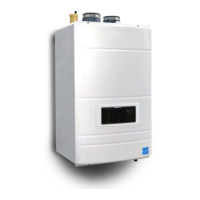
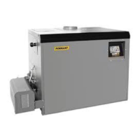
Model Name FTCF140
Gas Input Rate
MAX 140,000 Btu/h
MIN 28,000 Btu/h
Hot Water Capacity
35
°F
Rise 7.1 Gal
45
°F
Rise 5.5 Gal
77
°F
Rise 3.2 Gal
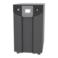
Installation Indoor / Floor stand type
Flue System Sealed Combustion Direct / Single / Concentric Vent/ SideWall Vent
Vent Run 2"(50ft) , 3"(100ft) Schedule 40 CPVC, PP
Gas Supply Pressure
NG 3.5" WC to 10.5" WC
LP 8.0" WC to 13" WC
Manifold Pressure
Gas Type LP NG
Vent size 2" VENT 3" VENT 2" VENT 3" VENT
FTCF140
Min re
-0.15
"
WC -0.216
"
WC -0.15
"
WC -0.216
"
WC
Low re
0.1
"
WC 0.079
"
WC 0
"
WC 0.002
"
WC
Power Supply
Main Supply 120V 60Hz / 6A
Maximum Power
Consumption
160W
Ignition System Direct Electronic Ignition / Automatic Flame Sensing
Burner System Single Orice Premixed Fuel Modulation Ceramic Infrared
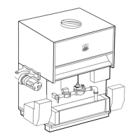
Gas Valve System Combination modulating (Current proportional)
Minimum Flow Rate 0.5 GPM
Dimensions W15.7" - H52.4" – D26.7"
Shipping Weight 230 lbs ( 104 kg )
Sub Heat Exchanger Water Capacity(DHW) Under 15 Gallon
Main Controller / Control Panel GTX-920CP / P-920C
Water Pressure Min 15 ~ Max 150 PSI
Connection Sizes
Cold Water Inlet / Hot
Water Outlet
3/4" NPT
Space Heating
Supply / Return
1" NPT
Gas Inlet 1/2" NPT
Materials
Casing Cold Rolled Carbon Steel
Heat Exchanger
Primary Heat Exchanger : Stainless Steel
Sub Heat Exchanger : Stainless Steel
Safety Devices
Flame Rod, Overheat Cut O Device, Gas Valve Operation
Detector, Exhaust Temperature High Limit Switch, Water
Temperature High Limit Switch
800.900.9276 • Fax 800.559.1583
(Customer Service, Service Advisors)
20 Industrial Way, Rochester, NH 03867 • 603.335.6300 • Fax 603.335.3355
(Applications Engineering)
1869 Sismet Road, Mississauga, Ontario, Canada L4W 1W8 • 905.238.0100 • Fax 905.366.0130
www.Laars.com
Document 4290B
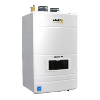
The FT Series, Floor-Standing, Gas Conversion Kit
pg 3 of 4
Manifold pressure
‘NG’ type combustibility ‘LP’ type combustibility
2" VENT 3" VENT 2" VENT 3" VENT
FTCF140
MAX Fire
-0.15
"
WC -0.216
"
WC -0.15
"
WC -0.216
"
WC
MIN Fire
0
”
WC 0.002
”
WC 0.1
”
WC 0.079
”
WC
FTCF199
MAX Fire
-0.134
”
WC -0.173
”
WC
MIN Fire
-0.015
”
WC -0.015
”
WC
Figure D
15.
Setup your combustion analyser and place the sensor
into the combustion test port
16.
Per Table B for Max Fire
,
change dip switch 6 to ON and 7 to OFF.
The unit will cycle up to MAX re.
17.
WAIT for your combustion analyser to stabilize. This may take up to 3 minutes depending on your combustion
analyser. Then check the CO
2
measurement for MAX re. Refer to Table D for acceptable MAX re
combustion readings. At this point, just record the CO
2
readings at MAX Fire. Do NOT attempt to adjust
CO
2
at MAX Fire. ONLY in MIN Fire, so...
18.
Per Table B for MIN Fire
,
change dip switch 6 to OFF and 7 to ON. The unit will cycle down to MIN Fire.
19.
WAIT for your combustion analyser to stabilize. Then check the CO
2
measurement at MIN re. Refer to
Table D for acceptable MIN re combustion readings.
20.
If CO
2
readings in Max Fire and MIN re are acceptable, then skip ahead to Step 23. If not, then open the
Gas Valve Adjustment Port by removing the cap screw with a 4mm Allen wrench. See Figure E.
21.
Then use the 4 mm Allen wrench to make a minor adjustment (1/8 turn) to either increase or decrease CO
2
.
Table B DIP Switch Settings
MBH N/A 140 N/A 199
ON OFF
MIN Fire Normal Operation
MAX Fire Normal Operation
NG Natural LP Propane
3” Vent Size
2” Vent Size
ON OFF ON ON
ON OFF OFF ON
OFF ON ON ON
DO
NOT
CHANGE
REFERENCE
ONLY.
CO
2
value
‘NG’ type combustibility ‘LP’ type combustibility
2" VENT 3" VENT 2" VENT 3" VENT
FTCF140
MAX Fire 8.5~10.5% 9.5~11 %
MIN Fire 8~10% 9~10.5 %
FTCF199
MAX Fire 8.5~10.0% 9.5~11 %
MIN Fire 8~10% 9~10.5 %
Table C
Table D