Page 52
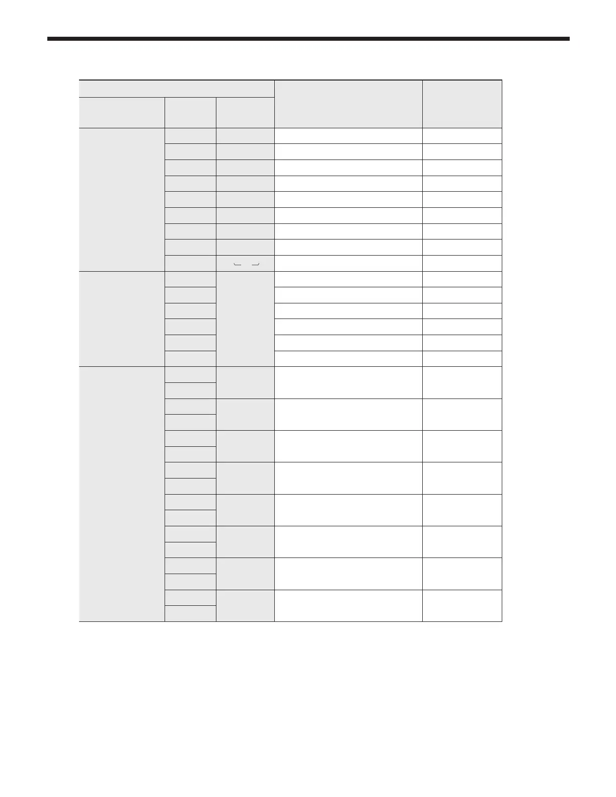
4.21 Electrical Connections
SECTION 4. Installation
Connector
Description
HT
SELV
#, Location, Type PIN Label
CN9
65001WS-12
1 - GROUND -
2 L Power Supply Line HT (120VAC)
3 CP1 Mixing Pump HT (120V~)
4 IT Igniter HT (120V~)
5 HEAT/CP2 Central Heating Pump HT (120V~)
6 GV Gas Valve HT (120V~)
7
-
- -
8 N Power Supply Neutral HT (120V~)
9-12
N
AC Power COM Line HT (120V~)
CN4
LWD1140-06D
1
FAN
Unuse -
2 GND SELV (26VDC)
3 VDD SELV (14VDC)
4 Fan power(start coil) SELV (26VDC)
5 Fan power(end coil) SELV (26VDC)
6 Fan speed feedback signal SELV (14VDC)
CN11
LWD1140-16
1
HWL Unuse SELV (12V~)
8
2
LWL Low Water Level Leakage Sensor SELV (12V~)
10
3
HD Central Heating Demand SELV (5V)
11
4
TH
Connect to the Display
Control(Thermostat)
SELV (14V)
12
5
APS
Jump (not used) SELV (14V)
13
6
EL
Jump (not used) SELV (14V)
14
7
BL Burner Limit SELV (14V)
15
8
HL Condensate Block SELV (14V)
16