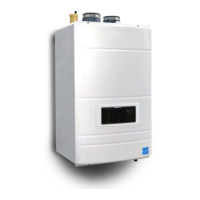
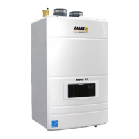
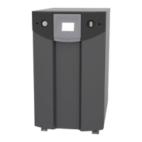
The FT Series Floor Standing, Combination Boiler
Page 49
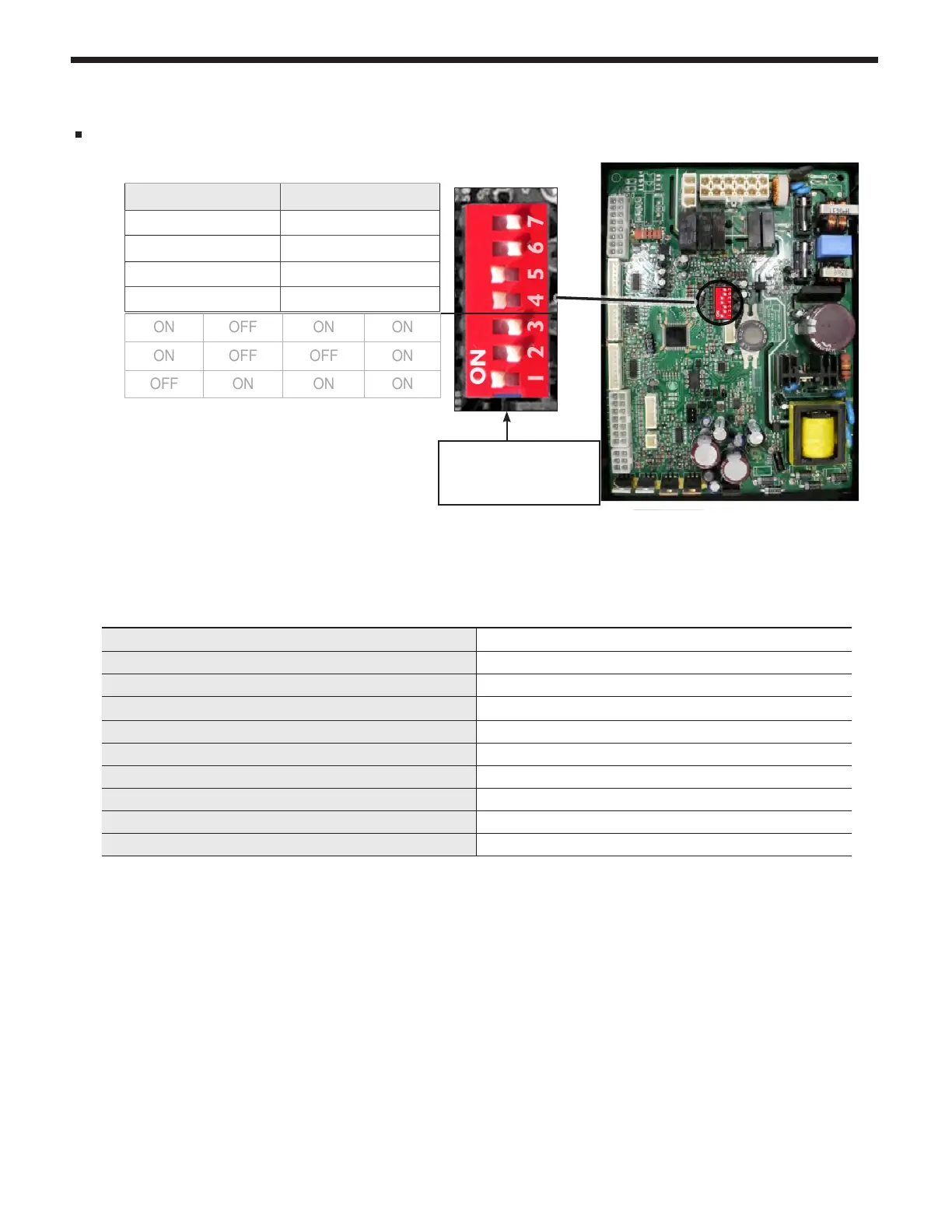
4.18 DIP Switches
System Control Setting
Maximum ame detecting voltage 2.4V
Pre-purge time (Tp) Maximum 10s, minimum 1s
Safety Time (igniting time) (Ts) 3s
Igniting interval time 10s
Post-purge time (Tip) 120S (1st : 60s + 2nd 60s)
Over-heating 1,2,3 protection detection time <3s
Pump1 post circulating time (T1pv) 60s
Pump2 post circulating time (T1pv) 60s
High & Low Water Level detection time <6s
High & Low Water Level Recover time <6s
DIP switches 6 and 7 have to be set in the OFF position when the boiler is running normally.
800.900.9276 • Fax 800.559.1583 (Customer Service, Service Advisors)
20 Industrial Way, Rochester, NH 03867 • 603.335.6300 • Fax 603.335.3355 (Applications Engineering)
1869 Sismet Road, Mississauga, Ontario, Canada L4W 1W8 • 905.238.0100 • Fax 905.366.0130
www.Laars.com
Document 4290C
The FT Series, Floor-Standing, Gas Conversion Kit
pg 3 of 4
Manifold pressure
Gas Type ‘NG’ Gas Type ‘LP’
2" VENT 3" VENT 2" VENT 3" VENT
FTCF140
MAX Fire
-0.15
"
WC -0.216
"
WC -0.15
"
WC -0.216
"
WC
MIN Fire
0
”
WC 0.002
”
WC 0.1
”
WC 0.079
”
WC
FTCF199
MAX Fire
-0.134
”
WC -0.173
”
WC
MIN Fire
-0.015
”
WC -0.015
”
WC
Figure D
15.
Setup your combustion Analyzer and
place the sensor into the combustion test port.
16.
Per Table B for Max Fire
,
change dip switch 6 to ON and 7 to OFF.
The unit will cycle up to MAX re.
17.
WAIT for your combustion Analyzer to stabilize. This may take up to 3 minutes depending on your combustion
Analyzer. Then check the CO
2
measurement for MAX re. Refer to Table D for acceptable MAX re
combustion readings. At this point, just record the CO
2
readings at MAX Fire. Do NOT attempt to adjust
CO
2
at MAX Fire. ONLY in MIN Fire, so...
18.
Per Table B for MIN Fire
,
change dip switch 6 to OFF and 7 to ON. The unit will cycle down to MIN Fire.
19.
WAIT for your combustion Analyzer to stabilize. Then check the CO
2
measurement at MIN re. Refer to
Table D for acceptable MIN re combustion readings.
20.
If CO
2
readings in Max Fire and MIN re are acceptable, then skip ahead to Step 23. If not, then open the
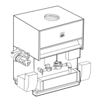
Gas Valve Adjustment Port by removing the cap screw with a 4mm Allen wrench. See Figure E.
21.
Then use the 4 mm Allen wrench to make a minor adjustment (1/8 turn) to either increase or decrease CO
2
.
Table B DIP Switch Settings
Photo shows a model
140 using 3" venting
and natural gas.
MBH 140 199
ON OFF
MIN Fire Normal Operation
MAX Fire Normal Operation
NG Natural LP Propane
3” Vent Size
2” Vent Size
ON OFF ON ON
ON OFF OFF ON
OFF ON ON ON
REFERENCE
ONLY.
CO
2
value
Gas Type ‘NG’ Gas Type ‘LP’
2" VENT 3" VENT 2" VENT 3" VENT
FTCF140
MAX Fire 8.5~10.5% 9.5~11 %
MIN Fire 8~10% 9~10.5 %
FTCF199
MAX Fire 8.5~10.0% 9.5~11 %
MIN Fire 8~10% 9~10.5 %
Table C
Table D