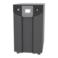
The FT Series Floor Standing, Combination Boiler
Page 53
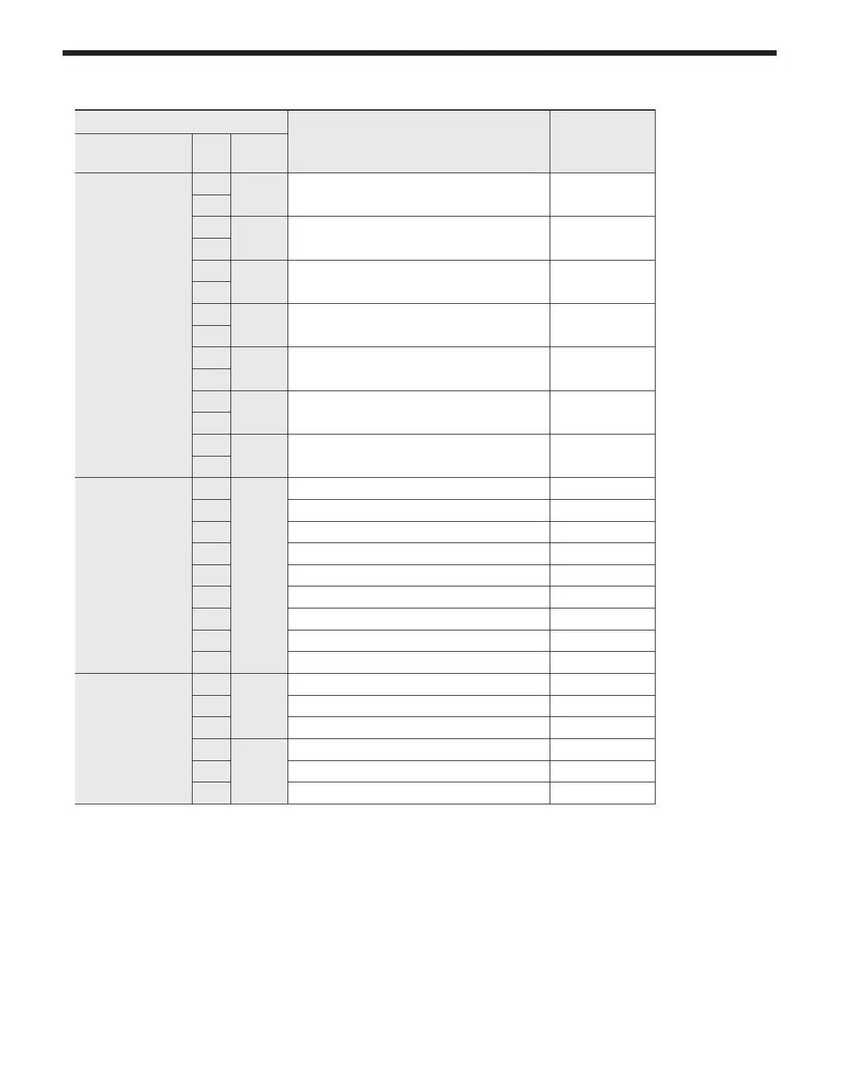
Connector
Description
HT
SELV
#, Location, Type PIN Label
CN7
LWD1140-14
1
F.S Flame Detect Sensor SELV (5VDC)
8
2
OP.S Operation water temperature sensor SELV (5VDC)
9
3
DH.S DHW temperature sensor SELV (5VDC)
10
4
I.S
CH Return sensor SELV (5VDC)
11
5
BG.S Exhaust temperature sensor SELV (5VDC)
12
6
ST.S Storage water temperature sensor SELV (5VDC)
13
7
SP.S Over heat temperature sensor SELV (5VDC)
14
CN14
SMW250-09D
1
IWM
GND SELV (14VDC)
2 DHM Stepper motor position SELV (14VDC)
3 VDD SELV (14VDC)
4 DHM Stepper motor coil X phase SELV (14VDC)
5 DHM Stepper motor coil Y phase SELV (14VDC)
6 VDD SELV (14VDC)
7 DHM Stepper motor coil /X phase SELV (14VDC)
8 DHM Stepper motor coil /Y phase SELV (14VDC)
9 Unuse -
CN3
SMW250-06D
1
APS
SEN-
SOR
VCC SELV (5V)
2
GND SELV (5V)
3
Voltage input SELV (5V)
4
FLUX1
VCC SELV (5VDC)
5 Water Flow Sensor SELV (5VDC)
6 GND SELV (5VDC)
4.21 Electrical Connections (continued)