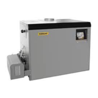
The FT Series Floor Standing, Combination Boiler
Page 39
4.13 Natural Gas to Propane Conversion (continued)
800.900.9276 • Fax 800.559.1583 (Customer Service, Service Advisors)
20 Industrial Way, Rochester, NH 03867 • 603.335.6300 • Fax 603.335.3355 (Applications Engineering)
1869 Sismet Road, Mississauga, Ontario, Canada L4W 1W8 • 905.238.0100 • Fax 905.366.0130
www.Laars.com
Document 4290C
The FT Series, Floor-Standing, Gas Conversion Kit
pg 2 of 4
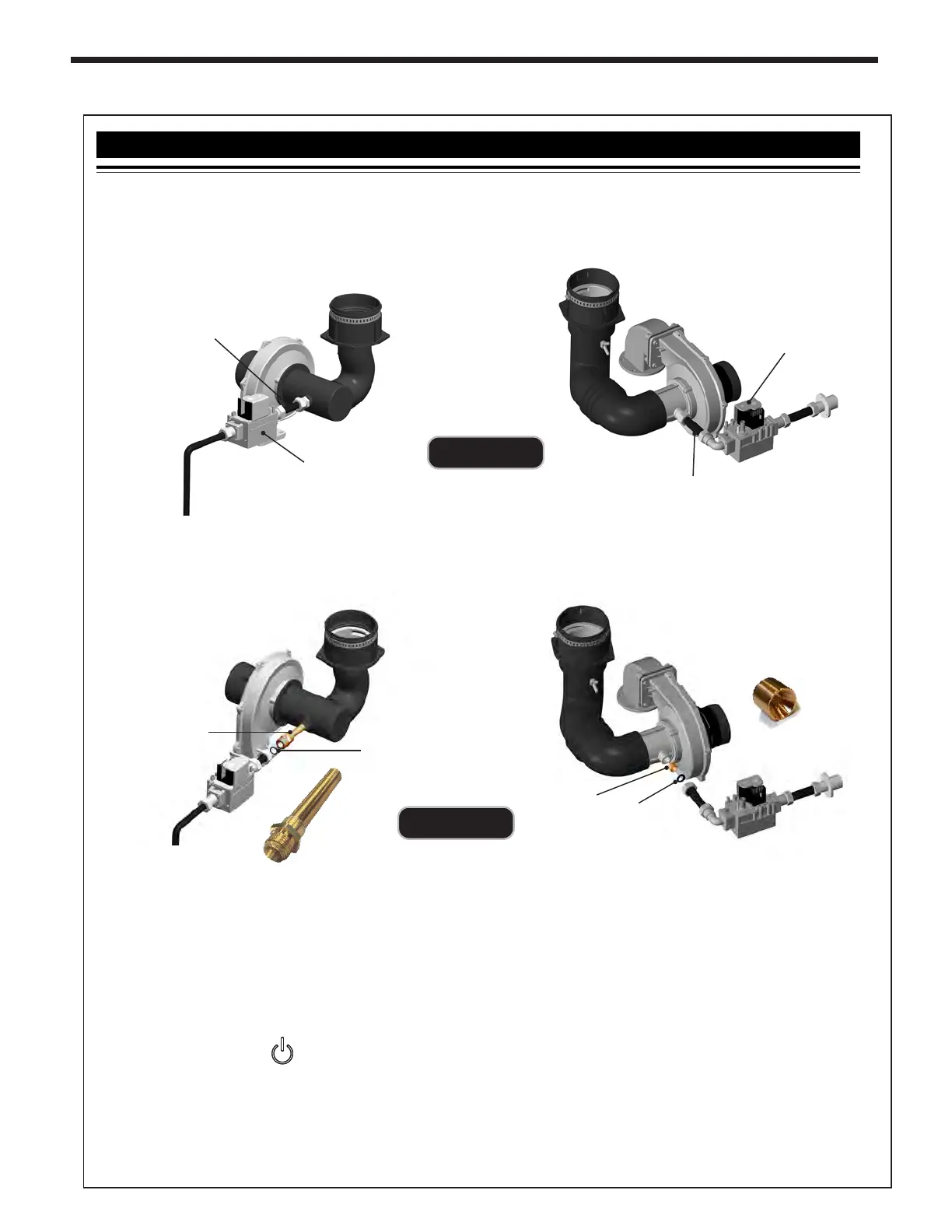
FTCF140
GAS VALVE
GAS INLET PIPE
GAS VALVE
GAS INLET PIPE
FTCF199
7.
Remove the existing natural gas nozzle or ori ce. If your unit is a FTCF199, note that the conical end of the ori ce
is towards the valve. Save the packing for re-use. See Figure C.
8.
Replace the old Nozzle (or Ori ce) with the new one for LP (propane).
Re-use the packing from previous.
9.
Return the Gas Inlet Pipe to its original position and tighten the Brass Fittings.
10.
Per Table B, set DIP Switch 5 to the ‘OFF’ setting (the #5 DIP switch setting for LP Propane is the OFF side).
11.
Turn ON the GAS and WATER supply to the FT.
12.
Turn ON the FT.
13.
Connect a manometer to the Manifold Pressure Port. See Figure E. For dual port manometers, use the
positive pressure side. Check for proper manifold gas pressure. Refer to Table C on next page.
14.
Establish a call for heat. You may need to disconnect the outdoor reset if you are making this gas conversion
during warm weather.
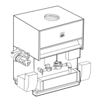
6.
Loosen the hex-nuts on the Gas Inlet Pipe and remove the nozzle or ori ce (See Figure C). Save the Packing
for re-use with the replacement Gas Ori ce.
NOZZLE
ORIFICE
PACKING
PACKING
FTCF140
FTCF199
3.
Using a Phillips screwdriver, remove the 4 screws on the Top Access Panel, and then lift out the Top Access Panel.
4.
Unthread the Front Panel Knob at the top of the front panel and then remove the entire panel. See Figure A.
5.
With the internal components exposed, locate the gas inlet pipe of your model. See Figure B.
Figure C
Figure B