= pÉêîáÅÉ=j~åì~ä=pmUMc^=L=pmUMc_= m~ÖÉ=P=ENUF=
=
-check Q1, Q2, Q3 (SP80FB).
It is now possible to increase the voltage across C8 and C9 (SP80FA) to approx. 300V without current inrush.
Measure across Q1 (SP80FB) collector and emitter with an oscilloscope. This oscilloscope should be connected to mains power
with an isolation transformer.
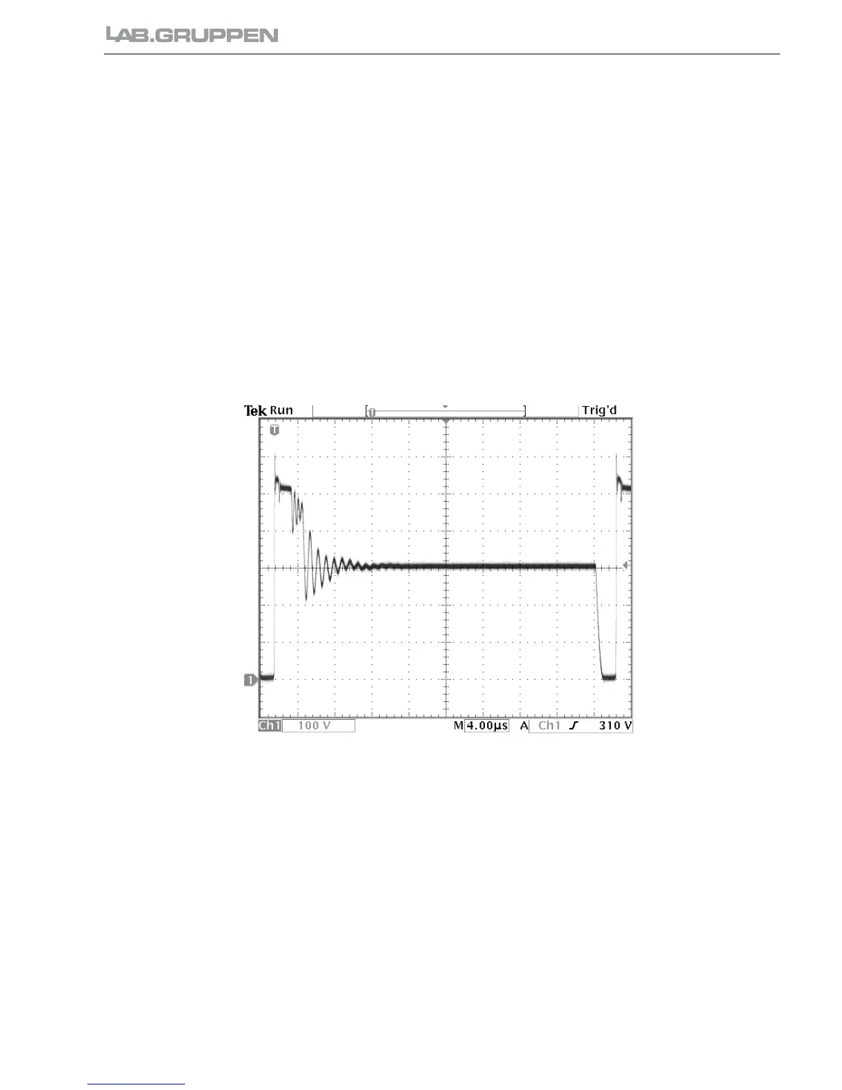
7) Turn VR3 slowly clockwise until a pulse is visible on the scope. The frequency is approx. 27 kHz (see figure1). If the
graph is seen, go to item 9).
8) If only narrow spikes is seen, check the following components.
a) D3, D4 (SP80FA) or the output circuits.
b) D1, C5, R1 (SP80FA) -makes U1 go into over voltage protection.
c) U1 -the output will remain low all the time.
9) Turn VR3 fully clockwise:
a) Check the output voltage on C12, C14 (SP80FA). Adjust with VR2.
b) Check the soft start circuit by turning the main switch on and off and look at the oscilloscope.
c) Increase the power by applying an audio signal to the amplifier and turn up the gain controls. -The pulse width will
increase.
d) Check the over/ under voltage protection circuits by turning the variac up to 280 VAC and down to 130 VAC. (No load)
Fig. 1

 Loading...