Do you have a question about the Lakeshore 211 and is the answer not in the manual?
Overview of the chapter's content, including description, specifications, and safety.
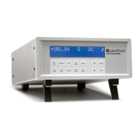
Details the Model 211's features, applications, and measurement capabilities.
Details measurement capabilities, sensor support, and resolution.
Describes the display type, units, annunciators, and keys.
Covers serial interface, baud rate, alarms, and actuators.
Details the two available relays, contacts, and ratings.
Specifies output modes, ranges, resolutions, and scales.
Lists the different models of the temperature monitor.
Lists accessories that come with the unit or are available separately.
General safety precautions for operation, service, and repair.
Warnings against operating in explosive atmospheres.
Instructions on avoiding live circuits and using qualified personnel.
Prohibits unauthorized modifications or substitute parts.
Instructions for cleaning the instrument exterior only.
Explains various safety symbols used in the manual.
Overview of installation procedures and safety guidelines.
Procedures for checking and unpacking the instrument.
Identifies connectors and ports on the rear panel.
Details the coaxial connector for the power supply.
Information on the universal input power supply.
Instructions for attaching the cable clamp for power cord security.
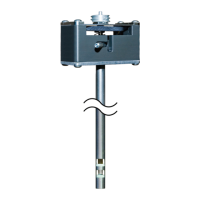
Introduces connecting sensors to the instrument input.
Details the pin assignments of the DB-25 input/output connector.
Discusses cable types and recommendations for sensor leads.
Importance and methods for shielding sensor leads to reduce noise.
Guidelines for proper instrument chassis grounding.
Importance of connecting sensor leads with correct polarity.
Explanation of the 4-lead measurement method.
How to use a 2-lead configuration when 4-lead is not feasible.
Techniques for minimizing measurement noise.
How to configure voltage or current analog output.
Describes the two relays and their control modes.
Instructions for using included brackets for panel mounting.
Information on available panel mount adapters.
Overview of operating instructions for the Model 211.
How to power the instrument on and off without a dedicated switch.
Explains the 6-digit LED display and annunciators.
Explains display annunciators and alarm messages.
Describes the four front panel keys and their functions.
Explains setting selection and data entry operations.
How to select the appropriate sensor type for the input.
How to select standard or user-defined sensor curves.
How to select display units (K, °C, °F, V/Ω).
Configuring high/low alarms and latching modes.
Configuring relay modes (manual, alarm-driven).
Configuring analog output mode (voltage/current) and ranges.
Formulas for converting analog output to temperature (K).
How to lock/unlock the front panel keypad.
Procedure to restore default instrument parameters.
How to enter and store custom sensor curves via serial interface.
Defines parameters for identifying and configuring a curve.
How to define breakpoints for sensor curves.
Overview of computer automation via serial interface.
Details the RS-232C serial interface standard.
Describes the 9-pin D-Subminiature connector and cabling.
Explains asynchronous timing, half duplex, and baud rate.
Describes character structure, parity, and terminators.
Defines commands, queries, responses, and chaining.
User program responsibilities for serial communication timing.
Steps to set up a Visual Basic program for serial communication.
Demonstrates using commands like *IDN?, KRDG?, INTYPE.
Tips for resolving common serial communication issues.
Steps for diagnosing existing communication problems.
Overview of available interface commands and their categories.
Overview of service procedures and consulting personnel.
Information for contacting Lake Shore for support.
Procedure for returning products for calibration, repair, or replacement.
Explains instrument hardware error messages.
Explains limit error messages related to input/output ranges.
Safety warnings and steps for removing/installing the enclosure.
Details the power, input/output, and serial connectors.
Suggested wiring diagrams for connecting to PCs.
Lists necessary PC, software, DMM, and resistors.
Overview of calibrating sensor input.
Steps for calibrating 10µA source and verifying 1mA source.
Process for determining input offset and gain errors.
Table correlating input types with calibration resistors.
Calibration requirements for voltage and current modes.
Steps to calibrate analog output in voltage mode.
Steps to calibrate analog output in current mode.
Overview of commands used for calibration.
Lists the different models of the temperature monitor.
Lists accessories that come with the unit or are available separately.
Lists available cryogenic wire types.
Lists silicon diode temperature sensors.
Introduction to the curve tables applicable to the Model 211.
Lists the declarations included in this appendix.
CE conformity statement for the Model 211 unit.
RoHS compliance statement for the Model 211 unit.
CE conformity statement for the Model 211 power supply.
RoHS compliance statement for the power supply.
CE conformity for older power supply models.
RoHS compliance for older power supply models.
Displays the instrument's menu hierarchy and settings.
| Input Channels | 1 |
|---|---|
| Temperature Sensor Type | platinum RTD |
| Accuracy | ±0.5 K |
| Sensor Excitation | 10 μA |
| Units | Kelvin (K), Celsius (°C), or Fahrenheit (°F) |
| Power Supply | 100-240 VAC, 50/60 Hz |