Installation
Inspection and Unpacking (Continued)
If the instrument must be returned for recalibration, replacement or repair, a
returned goods authorization (RGA) number must be obtained from a
factory representative before it is returned. The Lake Shore RGA procedure
is given in Paragraph 5.2.
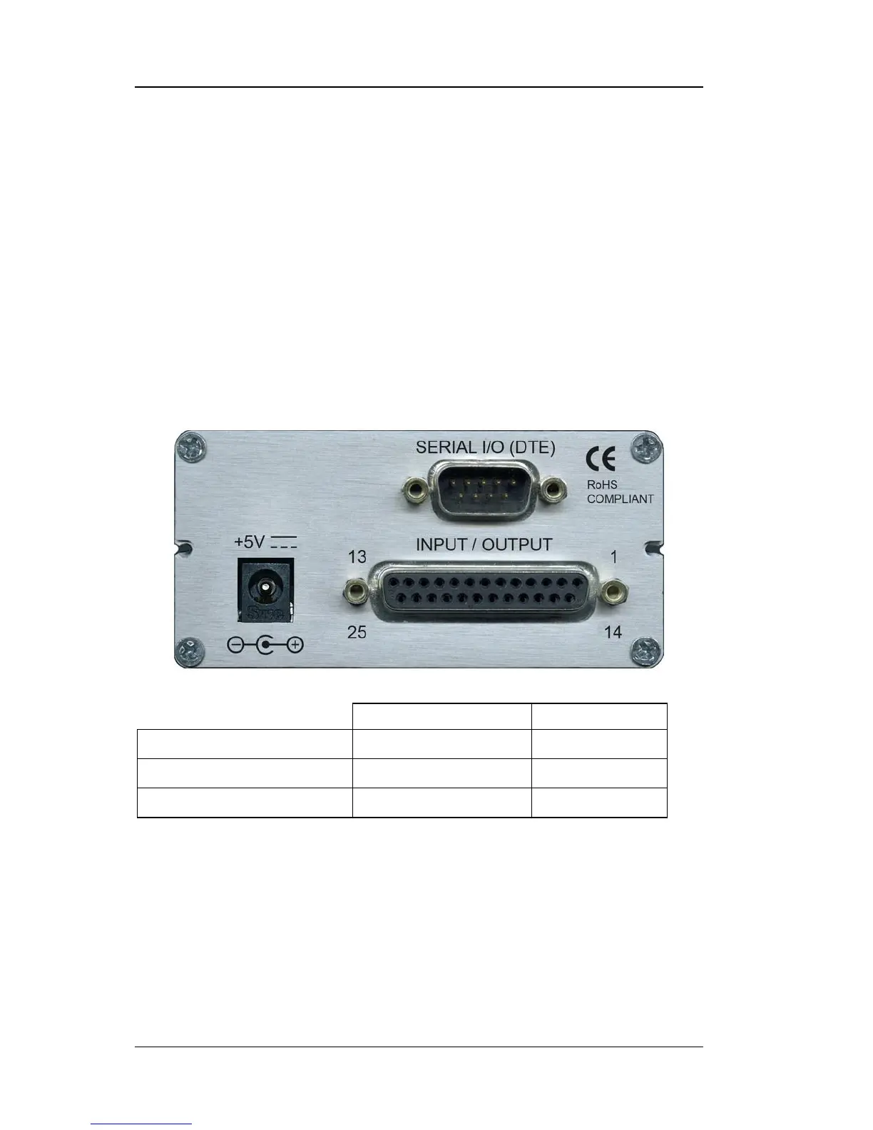
2.2 REAR PANEL DEFINITION
This paragraph describes the connectors on the rear panel of the Model 211.
See Figure 2-1. Readers are referred to paragraphs that contain installation
instructions and connector pin-outs for each feature. A summary of
connector pin-outs is provided in Paragraph 5.5.
CAUTION: Only make rear panel connections with power supply
disconnected.
211_Rear.jpg
Figure 2-1. Model 211 Rear Panel
2.3 POWER INPUT CONNECTOR
Power is supplied to the Model 211 through a coaxial connector located on
the rear panel of the instrument. There is no power switch on the
instrument, so it is off when not plugged in, or on when plugged in. Make
sensor connections before applying power to the instrument.
 Loading...