Installation
2.6.1 Input/Output Connector
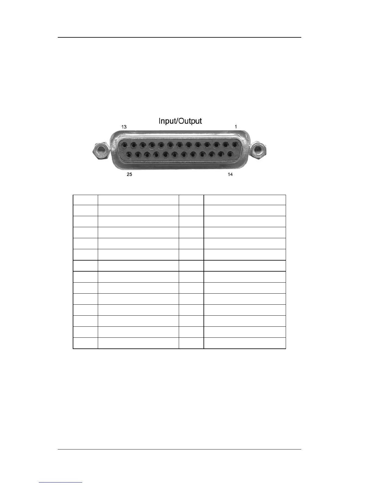
Sensors are connected to the Model 211 through the Input/Output connector
on the rear panel of the instrument. The Input/Output connector is also used
for the analog output and relay connections. Refer to Figure 2-3 for pin
descriptions.
P-211-2-3.bmp
Figure 2-3. Input/Output Connector
2.6.2 Sensor Lead Cable
The sensor lead cable used outside the cooling system can be much
different from what is used inside. Between the instrument and vacuum
shroud, heat leak is not a problem, but errors from noise pick up need to be
minimized. Larger conductor, 22 to 28 AWG stranded copper wire is
recommended because it has low resistance yet remains flexible when
several wires are bundled in a cable.