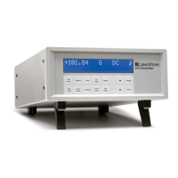
Operation
3.8 ANALOG OUTPUT SETUP
The Model 211 has a single analog output. It is normally configured to
provide an analog signal proportional to temperature to a strip chart
recorder or separate data acquisition system. Pins 6 and 18 on the DB-25
Input/Output connector are used for the analog output. See Figure 2-3.
The analog output is front panel configurable to be either a variable DC
voltage or current source. In voltage mode, the analog output can vary from
0 to 10 V with a resolution of 0.15 mV or 0.0015% of full scale. The output
can drive a resistive load of no less than 500 . The output is short-circuit
protected so the instrument is not harmed if the load resistance is too small.
However, this practice is not recommended as the additional load on
instrument power supplies causes noise on internal circuits.
In current mode the analog output can vary from 4 to 20 mA with a
resolution of 0.2 µA or 0.0015% of full scale. The output is limited by a
10 V compliance voltage so the largest resistive load that the output can
drive in current mode is 500 .
The analog output has two modes, voltage and current, and six ranges.
The ranges are listed in Table 3-3. The low output is the temperature that
produces zero output (0 V or 4 mA) and the high output is the temperature
that produces full output (10 V or 20 mA).
If no curve is selected for the input, the analog output range is fixed to
output a signal proportional to sensor units. Refer to Table 3-4.
NOTE: When a curve is selected for the input, the analog output always
works in kelvin no matter what units are displayed.
To begin analog output setup press the Select key and use the s or t key
to select ―0UtPUt‖ and press the Enter key. Analog output mode will be set
up first. Use the s or t key to choose between voltage mode or current
mode. Press the Enter key to store the analog output mode.
The next setting is analog output range. Refer to Table 3-3 and use the
s or t key to select a range for the analog output. Press the Enter key to
store the analog output range. The display will return to normal operation.