Input Gain Calibration (Continued)
2. Reset the calibration constants to their default values using the CALZ
and CALG commands.
Example:
Input Type: GaAlAs Diode
Zero Offset Reset Command: CALZ 1,1,0
Gain Reset Command: CALG 1,1,1
3. Attach the 0 (short) resistor standard to the input.
4. Via the interface obtain the input reading using the CALREAD?
command and record this number.
5. Program the offset calibration by providing the inverse of the value
read in the previous step using the CALZ command.
Example:
Input Type: GaAlAs Diode
CALREAD? Reading: 0.00005
Calibration Command: CALZ 1,1,-0.00005
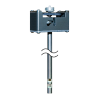
6. Select resistor standard for the range being calibrated from Table 5-1
and accurately determine value of the resistor to the tolerance shown.
7. Attach the resistor standard to the 211 sensor input. Be sure to connect
the resistor using proper 4-lead connection techniques.
8. Via the interface obtain the input reading using the CALREAD?
command and record this number.
9. Program the gain calibration by dividing the actual resistance of the
calibration resistor by the value read in the previous step and provide
the result using the CALG command. Note that the gain calibration
constant will always be within 5% of 1.00000.
Table 5-1. Calibration Table for Resistive Ranges