Table of Contents
LIST OF ILLUSTRATIONS
Figure No. Title Page
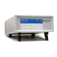
Figure 1-1. Model 211 Front Panel ............................................................ 1-1
Figure 2-1. Model 211 Rear Panel ............................................................. 2-2
Figure 2-2. Power Connector ..................................................................... 2-3
Figure 2-3. Input/Output Connector ........................................................... 2-4
Figure 2-4. Panel Mounting Details ........................................................... 2-9
Figure 2-5. 2111 and 2112 Panel Mount Adapters .................................. 2-10
Figure 3-1. Model 211 Display .................................................................. 3-2
Figure 5-1. Power Connector ..................................................................... 5-4
Figure 5-2. Input/Output Connector ........................................................... 5-4
Figure 5-3. RS-232 (DTE) Connector ........................................................ 5-5
LIST OF TABLES
Table No. Title Page
Table 1-1. Temperature Range of Typical Lake Shore Sensors ................ 1-2
Table 1-2. Sensor Input Performance Chart ............................................... 1-6
Table 3-1. Sensor Input Types ................................................................... 3-4
Table 3-2. Standard Curves ........................................................................ 3-5
Table 3-3. Analog Output Range Scales .................................................... 3-9
Table 3-4. Analog Output Scales in Sensor Units ...................................... 3-9
Table 3-5. Conversion Parameters for Temperature in K .......................... 3-9
Table 3-6. Model 211 Default Values ...................................................... 3-10
Table 3-7. Recommended Curve Parameters ........................................... 3-12
Table 4-1. Serial Interface Specifications .................................................. 4-3
Table 4-2. Serial Interface Program Control Properties ............................. 4-6
Table 4-3. Visual Basic Serial Interface Program ...................................... 4-8
Table 4-4. Interface Commands (Alphabetical Listing) ........................... 4-13
Table 5-1. Calibration Table for Resistive Ranges .................................... 5-9
Table A-1. Lake Shore DT-470 Silicon Diode (Curve 10) ....................... A-1
Table A-2. Lake Shore DT-670 Silicon Diode ......................................... A-2
Table A-3. CTI Curve C Silicon Diode .................................................... A-3
Table A-4. Lake Shore PT-100/-1000 Platinum RTD Curves .................. A-4