12
3 Functional Description
3.4 Basic circuit diagram
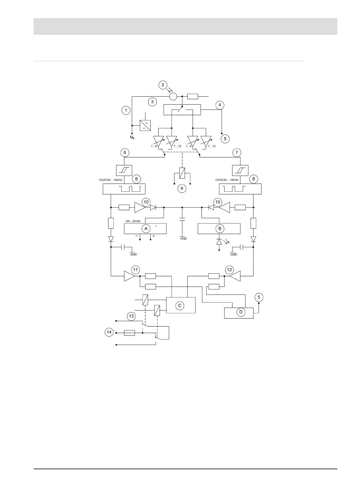
Fig. 3-1 Basic circuit diagram
A Intensity remote indicator C Self-monitoring
B Visual intensity indicator D Monitoring cycle
1 Stabilisation 8 Digital band pass
2 Flame sensor 9 Sensitivity selector switch
3 Detector 10 Safe de-coupling
4 Switch-over contact 11 Switching amplifier channel A
5 Cycle 12 Switching amplifier channel B
6 Channel A 13 Output relay
7 Channel B 14 Output contacts