42
9 Appendix
9 Appendix
9.1 Layout of the Operational Controls
9.1.1 F200K1 ... in the State as Delivered
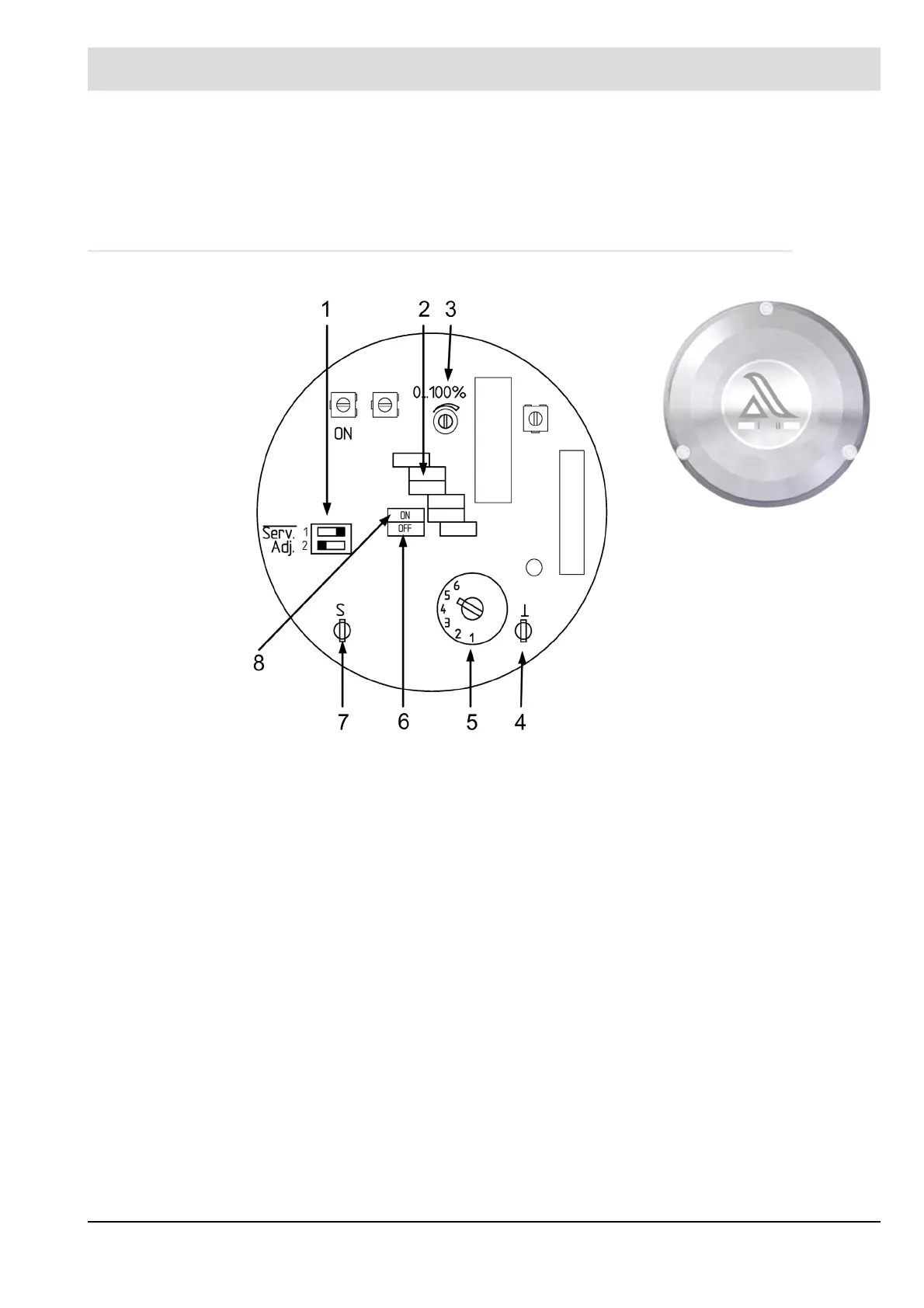
Fig. 9-1 Control and operating elements F200K1
Fig. 9-2 Housing cover F200K
1 - Serv. Service switch, according to chapter 7.1.6 Service - Switch Serv.Adj.- Adjust, according to chapter
7.1.1 Intensity Indicator Including the 'Adjust' Function and chapter 7.2.4 Settings
2 - Intensity indicator for flame signal in the range of 0 ... 100 %
3 - Start-up suppression, according to chapter 7.2.4 Settings
4/7 - Measuring points to measure the flame radiation received by the F200K according to chapter 7.2.4 Settings
5 - Sensitivity switch for gradual increase and/or decrease of sensitivity (amplification) of the compact flame
detector in 6 level, according to chapter 7.2.4 Settings
6 - LED (red): Indication ’Flame Out’ state
8 - LED (green): Indication ’Flame In’ state