Home
Lamtec
Industrial Equipment
F200K
Lamtec F200K User Manual
4
of 1
of 1 rating
74 pages
Give review
Manual
Specs
To Next Page
To Next Page
To Previous Page
To Previous Page
Loading...
50
9
Appendix
9.4.2
Interfacing with FMS
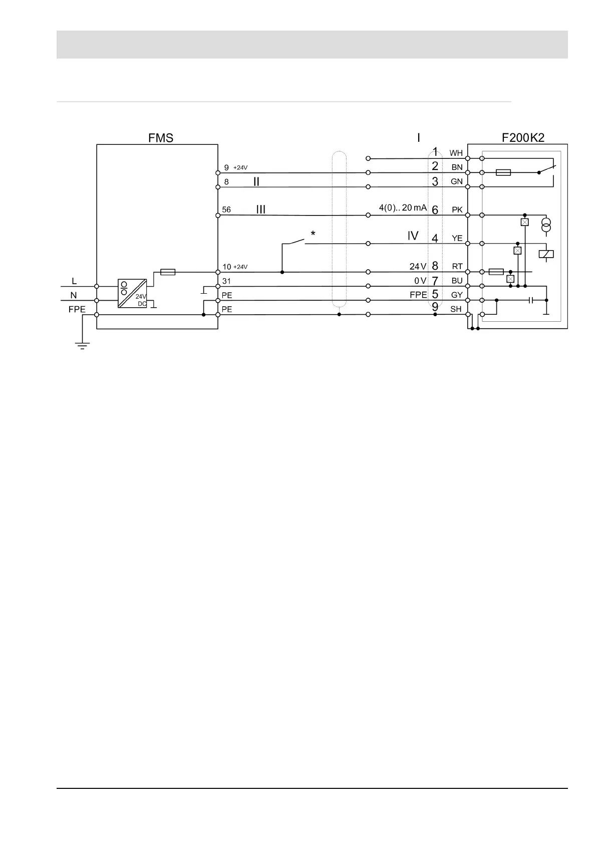
Fig. 9-13 Interconnection F200K2 with FMS
I
- Connection cable
WH
- white
PK
- pink
BU
- blue
II
- Flame signal
BN
- brown
YE
- yellow
GY
- grey
III
- Flame intensity
GN
- green
RT
- red
Sch
- shield
IV
- Range
*Use application-related
50
52
Table of Contents
Default Chapter
3
Table of Contents
3
1 General Information
6
Validity of These Instructions
6
Purpose
6
Target Group
7
Safekeeping of the Manual
7
2 Safety
8
For Your Safety
8
How to Use the Information
8
Product Safety
9
Product-Specific Dangers
9
3 Functional Description
11
Rating Plate
11
Mode of Operation
12
Basic Circuit Diagram
13
4 Technical Data
16
Life Cycle
19
5 Selection Criteria
20
6 Information for Mounting and Installation
21
Mounting - Basic Instructions
21
Safety
21
UL Listed
21
Basic Mounting Instructions
22
Installation
24
External Installation
24
Device Connection
25
7 Instructions on Commissioning and Maintenance
26
Display and Operational Controls
26
Intensity Indicator Including the 'Adjust' Function
26
Operating State - Indication
26
Operating Mode - Display
26
Sensitivity - Switch
27
Frequency - Switch
27
Service - Switch Serv
27
Adjust - Switch
27
Measuring Points
28
Commissioning
28
General Information
28
Flame Out' State
28
Flame In' State
28
Operating Mode Switchover
28
Special Points to Note When Using the Device in Explosion-Proof Areas
29
Preparations
31
Checking the Compact Flame Scanner
31
Alignment
31
Optics
31
Settings
32
Sensitivity
32
Alignment with Adjustment Function
32
Measuring Points
33
Frequency Settings
33
Start-Up Suppression
34
Switch-Off Test - Check the Correct Setting
35
Fault on Flame Detection
35
Interference
35
Exceeding the Permissible Ambient Temperature
35
Faults During Ignition
36
Faults During Operation
36
Troubleshooting
37
Commissioning Flow Chart
38
Maintenance
40
General Information
40
Instructions on Troubleshooting
40
Flame Scanner Testing Device Replace Battery
41
8 Warranty and Delivery Terms
42
9 Appendix
43
Layout of the Operational Controls
43
F200K1
43
F200K2
44
Dimensions
45
F200K and F200K Ex-II (Hazardous Area 2.22) Compact Flame Scanner
45
F200K2
46
Connection Housing FG 24 Ex
47
Circuit Diagrams
48
Circuit Diagram F200K1
48
Circuit Diagram F200K2
49
Examples of Application
50
Interfacing with ETAMATIC
50
Interfacing with FMS
51
10 Accessories
52
FN20, FN30-20 Power Supply
52
Purpose
52
Technical Data
52
Pin Assignment
55
Weather Shield
57
Adjustable Holding Devices
58
Fh30-10
58
FH40-10 (for IR and UV, with Ball-And-Socket-Joint and Purge Air Connection)
59
FV40-10 (for IR and UV, with Ball-And-Socket-Joint and Purge Air Connection)
60
Cooling Air Housing FS50
62
Cooling Air Housing with Ball-And-Socket Joint FS51
63
FS56 (Adjustable, Demountable, with Cooling Air Housing)
64
Installation in the Cooling Air Housing
65
Flame Scanner Testing Device
66
Connection Cable AK01
68
Purpose
68
Technical Data
68
Fiber Optic
69
11 Commissioning Protocol
71
12 EU Declaration of Conformity
72
Other manuals for Lamtec F200K
Quick Reference
18 pages
4
Based on 1 rating
Ask a question
Give review
Questions and Answers:
Need help?
Do you have a question about the Lamtec F200K and is the answer not in the manual?
Ask a question
Lamtec F200K Specifications
General
Brand
Lamtec
Model
F200K
Category
Industrial Equipment
Language
English
Related product manuals
Lamtec BurnerTronic BT320
48 pages
Lamtec BurnerTronic BT300
48 pages
Lamtec BurnerTronic BT340
48 pages