61
10 Accessories
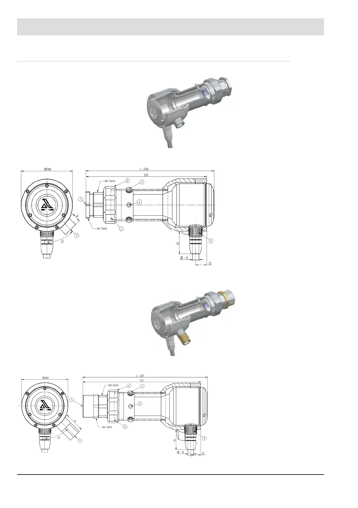
10.3.5 Cooling Air Housing FS50
Fig. 10-14 Cooling air housing FS50
Cooling air housing FS50-2 with cooling air connection NPT
Fig. 10-16 Cooling air housing FS50-2
Fig. 10-15 Cooling air housing FS50 dimension drawing
1 Pipe connector (boiler) Rp1"
2 Sealing ring 56x42x2
3 3x setting screws M6 - nylon
4 3x removable rubber buffers
(discharge of cooling air)
5 Cable connector with screwed
connection
6 Detachable connection
8 Kt SW 66 (lens cleaning)
7 Cooling air connection Rp1/2"
Fig. 10-17 Cooling air housing FS50-2 dimension drawing
1 Pipe connector (boiler) Rp1 1/2 "
2 Sealing ring 56x42x2
3 3x setting screws M6 - nylon
4 3x removable rubber buffers
(discharge of cooling air)
5 Cable connector with screwed
connection
6 Detachable connection
8 Kt SW 66 (lens cleaning)
7 Cooling air connection Rp 1/2"
NPT