47
9 Appendix
9.3 Circuit Diagrams
DANGER!
The output contacts of the Flame scanner are approved for use with SELV or PELV only.
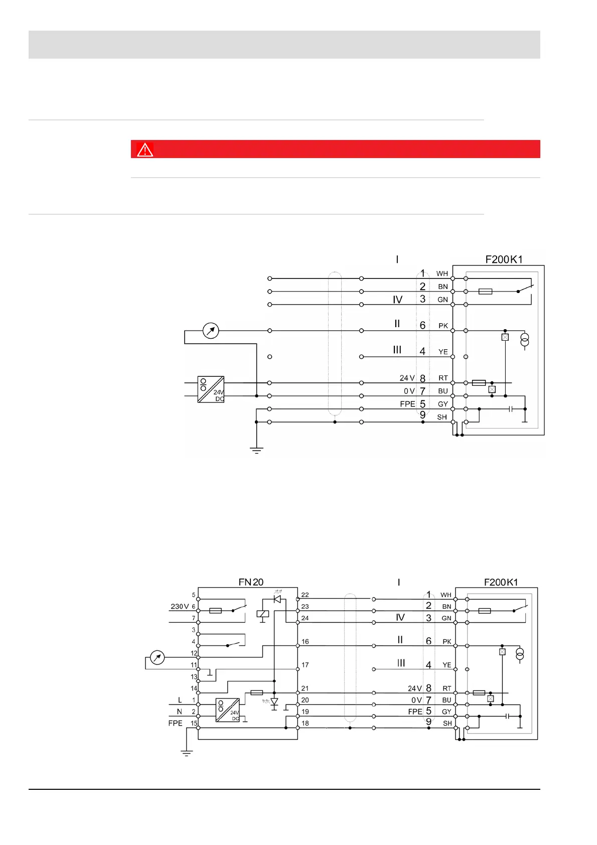
9.3.1 Circuit Diagram F200K1 ...
Fig. 9-8 Connection diagram F200K1...
Fig. 9-9 Connection diagram F200K1... with power pack FN 20
I - Connection cable WH - white PK - pink BU - blue
II - 0/4 ... 20 mA BN - brown YE - yellow GY - grey
III - Range without any function (F200K only) GN - green RT - red SH - shield
IV - Flame signal