PLMNL0286 REV. B, Effective Date: 06/06/19 9 FiberMINI
®
with Auto Focus (AF) Operation Manual
3 Electrical Installation and
Operation
Laser Mechanisms offers multiple control box
styles to accommodate your application.
For more info on using the DeviceNet,
EtherNet/IP and Modbus TCP control boxes,
see Section 3.2.
See your Laser Mechanisms Sales Engineer
for more control box models and other details.
The FiberMINI
®
AF requires a control cable
designed with wires in twisted pairs. There are
(2) standard options:
3.1 Electrical Connections
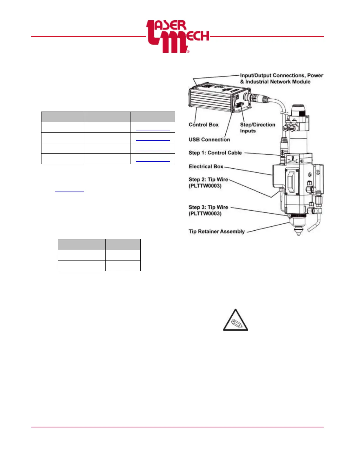
3.1.1 Connections to the Head
There are (3) cable connections to the
head.
The control cable (PLCAB0608 or
PLCAB0701) connects at the top of
the electrical box.
The straight end of the tip wire
(PLTTW0003) connects at the
bottom of the electrical box.
The right angle end of the tip wire
connects at the tip retainer
assembly.
See Figure 12.
Figure 12
For steps 1 to 3, see Figure 12.
1. Insert the female end of the control
cable into the top of the electrical
box.
2. Insert the straight end of the tip
wire into the bottom of the electrical
box.
It may be helpful to wrap
the tip wire around the tip
retainer assembly during
installation.
3. Insert the right angle end of the tip
wire into the tip retainer assembly.