PLMNL0286 REV. B, Effective Date: 06/06/19 21 FiberMINI
®
with Auto Focus (AF) Operation Manual
3.4 Electrical Grounding and Noise
The capacitive sensing circuitry contained
in the FiberMINI
®
AF cutting head
measures minute changes in electrical
capacitance between the tip and earth-
ground to determine tip-to-part standoff
distance. In order for this circuit to function
properly, connect the part and the cutting
head to a good earth ground.
The ideal is to establish the ground
from a ground rod (approximately 2
meters in length) located near the
base of the machine and driven into
the ground.
Run a large gauge (1.6mm diameter
or larger) ground wire from the ground
rod to the part.
Run a separate wire from the ground
rod to the FiberMINI
®
AF.
Electrical noise can create height-sensing
issues. Large electric motors, arc welders
and other devices may be a source of
significant electrical noise. In order to
eliminate this noise, it may be necessary
to connect a ground wire to the chassis of
any such device near the process.
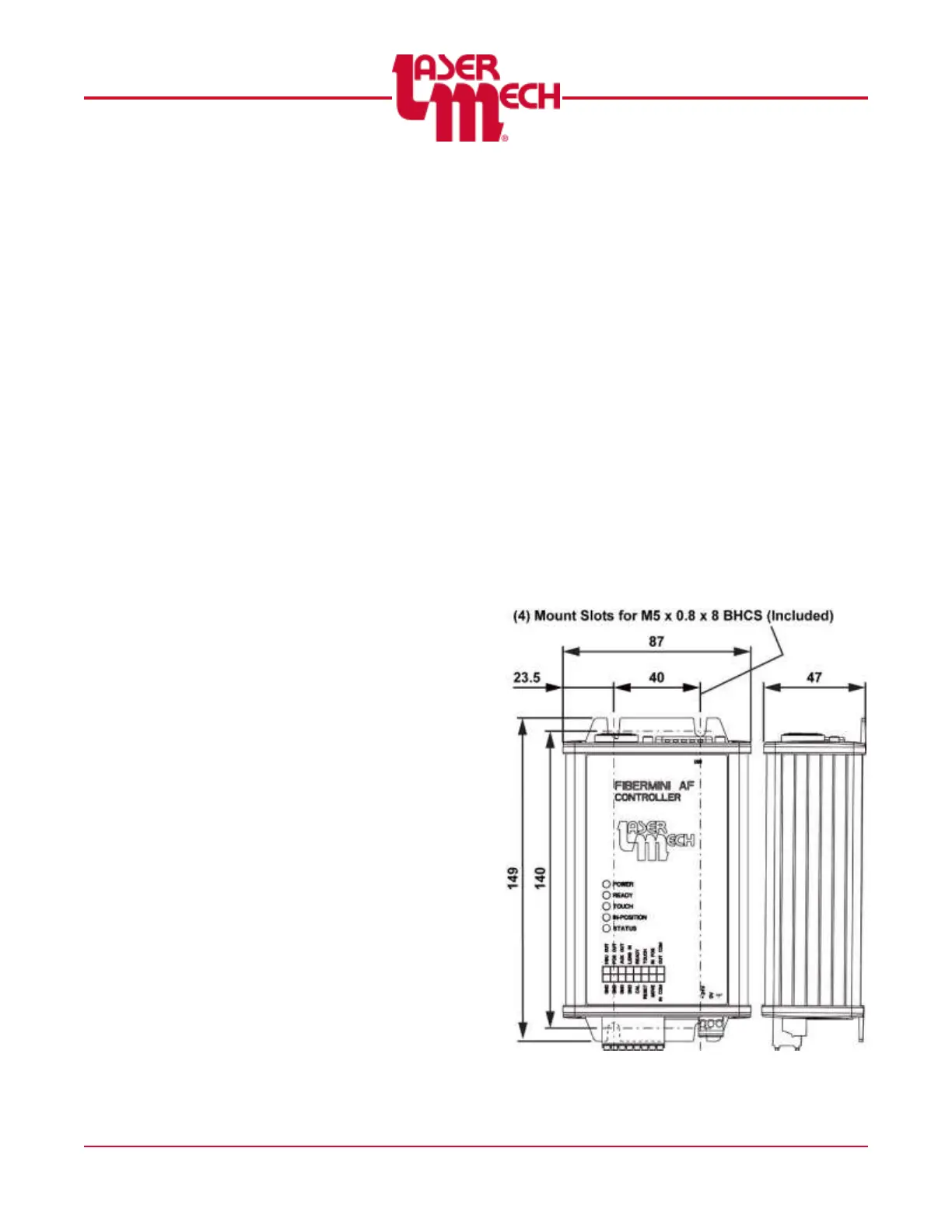
3.5 Control Box Mounting
Figure 20 illustrates the mounting pattern
for any of the control boxes and uses the
discrete I/O control box (PLCSA0081) as
an example.
Important things to consider when
mounting any of the control boxes:
Standard cable length is:
8 meters (PLCAB0608)
OR
20 meters (PLCAB0701).
Easy access for maintenance.
Mounting such that debris from the
process is not directed at the control
box.
Mounting in an area where there are
no water leaks or oils from hydraulic
lines.
Figure 20