PLMNL0286 REV. B, Effective Date: 06/06/19 24 FiberMINI
®
with Auto Focus (AF) Operation Manual
There are 3 digital inputs (Cal, Reset
and Move) available through the
terminal block connection.
All inputs are momentary signals
that trigger on a low to high
transition.
DIGITAL INPUTS
The Input Common allows users to
configure the inputs for either
sourcing or sinking.
~ Connect In Com to 24V DC for
sinking outputs (0V active).
~ Connect In Com to 0V DC for
sourcing outputs (24V active).
3.8 Calibration Procedure
The Calibrate input is a request for sensor
calibration. The calibration should take
place with the tip about 12mm away from
a grounded metallic surface at least
100mm in diameter.
The calibration must be performed at
power up and preferably every cycle.
Note: The recommendation is to
calibrate the tip every time the
head is in a retracted position.
The calibration procedure takes
~150ms and will ensure proper
tip standoff is maintained.
Calibrating at a standoff greater than
12mm will result in standoff readings that
are slightly less than the optimum level.
Calibrating at a standoff less than 12 mm
will result in standoff readings that are
slightly more than the optimum level.
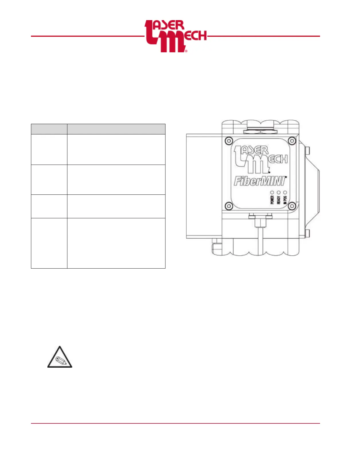
3.9 Head Indicator Lights
The electrical box on the head has (3)
indicator lights. See Figure 22.
Figure 22
The indicator light labeled POWER
illuminates in green when power is
supplied and the head has fully
initialized.
If initialization fails, the light
illuminates in amber.
The indicator light labeled READY
illuminates in green when the READY
output is active. The light illuminates
in red when a temperature fault is
detected within the head.
The indicator light labeled IN-POS
illuminates in green when the lens is
located at the target position. The light
illuminates in red when the servo is
shut off due to a position fault,
sending the lens to the fully retracted
position.