CS3E-E Series EtherCAT Closed Loop stepper drive User Manual
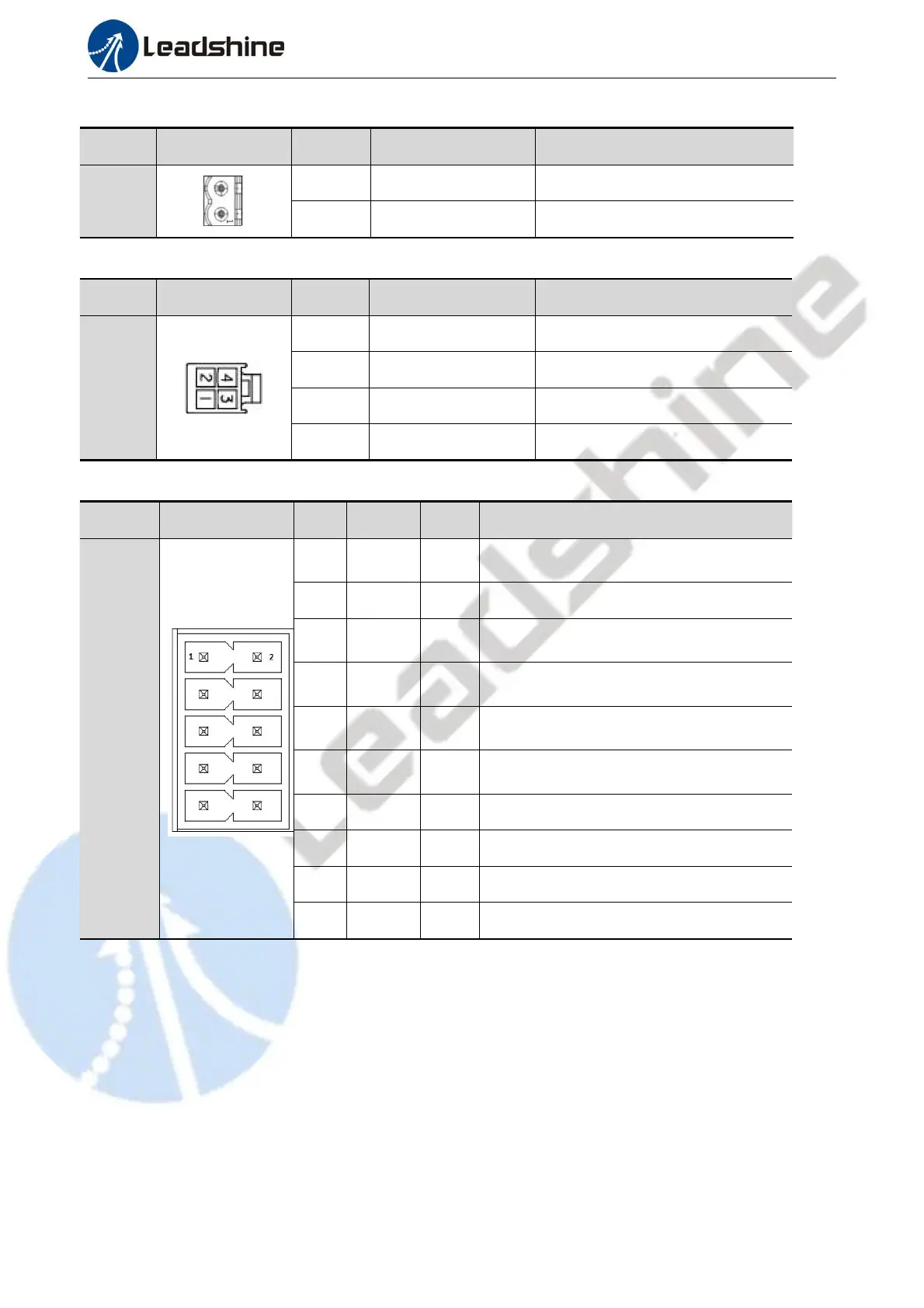
3.3.2 CN1-Input Power Connector
3.3.3 CN2-Motor Connector
3.3.4 CN3-I/O Signals Connector
Configurable Single-ended Digital Input 5,12V - 24V,
10KHz,
Negative Limit (default)
Configurable Single-ended Digital Input 6, 12V - 24V,
10KHz,GPIO
Configurable Single-ended Digital Input 3,12V - 24V,
10KHz,
Home switch (default)
Configurable Single-ended Digital Input 4,12V - 24V,
10KHz,
Positive Limit (default)
Configurable Single-ended Digital Input 1,12V - 24V,
10KHz,
Touch Probe 1 (default)
Configurable Single-ended Digital Input 2,12V - 24V,
10KHz,
Touch Probe 2 (default)
Common anode of external input signals
Common ground of digital output signals
Configurable Single-ended Digital Outputs 1,OC
output,Max. 30V/100mA. Alarm output (default)
Configurable Single-ended Digital Outputs 2,OC
output,Max. 30V/100mA. Brake output (default)
Remark:
(1) I/O interface and corresponding parameter setting refer to chapter 4.3
(2) In Leadshine MotionStudio,digital input(DI) and digital output(DO) are displayed as SI and SO.